
Anti-interference method for high-frequency partial discharge signal detection

A technology of discharge signal and partial discharge pulse, applied in the direction of testing dielectric strength, etc., can solve the problem of information redundancy and time-consuming calculation

Inactive Publication Date: 2014-03-26
XI AN JIAOTONG UNIV +1
View PDF4 Cites 39 Cited by
  • Summary
  • Abstract
  • Description
  • Claims
  • Application Information

AI Technical Summary

Problems solved by technology

[0007] Wavelet analysis uses discrete wavelet transform in practical application, which overcomes the shortcomings of continuous wavelet transform, such as information redundancy and time-consuming calculation.

Method used


Image

  • Anti-interference method for high-frequency partial discharge signal detection
  • Anti-interference method for high-frequency partial discharge signal detection
  • Anti-interference method for high-frequency partial discharge signal detection

Examples


Embodiment 1

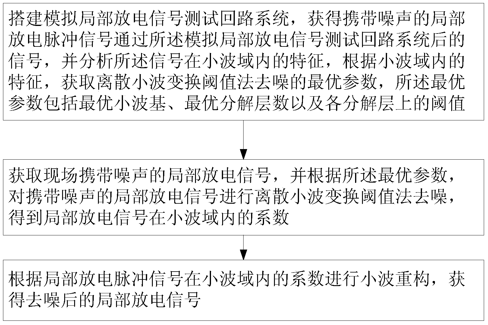
[0071] The invention aims to establish a wavelet threshold denoising method with optimal parameters, so as to be used in the denoising work of partial discharge detection. First of all, the present invention builds a simulated partial discharge detection system, and uses the wavelet threshold method to process the noisy partial discharge signal; then, according to the established index set for evaluating the denoising effect, the different denoising effects are comprehensively judged, Thus the optimal parameter configuration of the wavelet threshold denoising method is obtained.

[0072] see figure 1 As shown, the anti-interference method for high-frequency partial discharge signal detection provided by the present invention comprises the following steps:

[0073] 1) Build a simulated partial discharge signal test loop system, obtain the signal after the partial discharge pulse signal carrying noise passes through the simulated partial discharge signal test loop system, and a...

Embodiment 2

[0129] The following is a specific implementation example of the optimal parameter wavelet threshold denoising method given by the inventor.

[0130] 1. Laboratory simulation verification

[0131] The inventor took the XLPE cable as the partial discharge detection object. Firstly, the laboratory simulation test was carried out to verify the denoising effect of the optimal parameter wavelet threshold denoising method under the condition of high signal-to-noise ratio and various noise types. . The partial discharge test circuit built in the laboratory is as follows: Figure 16 shown. Figure 17 It shows that when Gaussian white noise is superimposed to a signal-to-noise ratio of -11 decibels, the simulated partial discharge pulse signal is shown in figure (a), and the result obtained after optimal parameter wavelet threshold method denoising is shown in figure (b). Figure 18 For when multiple noise signals are superimposed to a signal-to-noise ratio of -10 decibels, the simu...


PUM


Abstract

The invention discloses an anti-interference method for high-frequency partial discharge signal detection. The anti-interference method includes the steps of 1, building partial discharge signal simulation testing circuit system to acquire signals which are generated from local discharge pulse signals carrying noises after passing through the partial discharge signal simulation testing circuit system, and analyzing characteristics of the signals within a wavelet domain to acquire optimal parameter that is denoised by a discrete wavelet transform based threshold process; 2, acquiring the field partial discharge signals carrying noises, and acquiring the coefficient of the partial discharge signals within the wavelet domain by denoising the partial discharge signals carrying noises by the discrete wavelet transform based threshold process according to the optimal parameter; 3, performing wavelet reconstruction according to the coefficient of the partial discharge pulse signals within the wavelet domain to acquire the denoised partial discharge signals. The signals are denoised by firstly performing threshold processing to decomposition coefficients of different dimensions by threshold selection and then performing wavelet transform.

Description

technical field [0001] The invention relates to the field of cable partial discharge detection, in particular to an anti-interference method for high-frequency partial discharge signal detection. Background technique [0002] Partial discharge behavior is the main cause of insulation degradation and eventual failure of high-voltage electrical equipment. The occurrence of partial discharge is accompanied by phenomena such as sound, light, electricity, and heat. The detection method of partial discharge signal is based on the detection and conversion of these phenomena. Among them, the electrical measurement method refers to the method of measuring partial discharge based on various electrical phenomena, such as the method of detecting the loop pulse current caused by the exchange of charges that occurs during discharge, which is called the pulse current method (ERA method). The ERA method can correct the apparent discharge charge according to the equivalent circuit of parti...

Claims


Application Information

Patent Timeline
IPC IPC(8): G01R31/12
Inventor 徐阳张翔胡晓崔江静孙廷玺廖雁群
Owner XI AN JIAOTONG UNIV
Learn More