Circular polarization light board and display device
A technology for circularly polarized light and display devices, which is applied in the directions of polarizing elements, optics, optical elements, etc., and can solve problems such as difficult circularly polarized light plates
- Summary
- Abstract
- Description
- Claims
- Application Information
AI Technical Summary
Problems solved by technology
Method used
Image
Examples
Embodiment 1
[0334] [Preparation of composition for retardation layer formation]
[0335] The following components were mixed, and the obtained mixture was stirred at 80° C. for 1 hour to obtain a composition for retardation layer formation.
[0336] Compound A1 and Compound A2 were synthesized according to the method described in JP-A-2010-31223.
[0337] Compound A1 (80 parts):
[0338]
[0339] Compound A2 (20 parts):
[0340]
[0341] Polymerization initiator (6 parts):
[0342] 2-Dimethylamino-2-benzyl-1-(4-morpholinophenyl)butan-1-one
[0343] (イルガキユア369; manufactured by Ciba Specialty Chemical Co., Ltd.)
[0344] Leveling agent (0.1 part): Polyacrylate compound (BYK-361N; manufactured by BYK-Chemie
[0345] Solvent: mixed solvent of o-xylene (300 parts) and cyclopentanone (130 parts)
[0346] [Preparation of composition for photo-alignment film formation]
[0347] The following components were mixed, and the resulting mixture was stirred at 80°C for 1 hour to obtain a c...
Embodiment 2
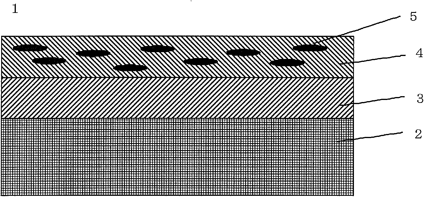
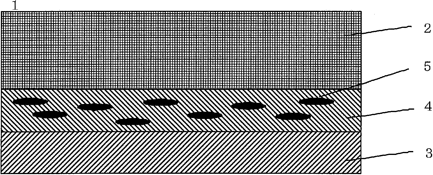
[0399] Same as embodiment 1, form the first alignment film (the polarization direction of the polarized UV is 45° with respect to the long-side direction of the base film) on one face of the transparent base film, form the retardation layer on this photo-alignment film . Then, after forming a protective layer on the phase difference layer, form a second alignment film (the polarization direction of polarized UV is 0° with respect to the long side direction of the substrate film), and further form a polarizing layer on this photo alignment film, Make this circular polarizing plate.
[0400] Similar to Example 1, the transparent base film of the produced circularly polarizing plate was bonded to the reflector using an adhesive, and the reflectance was measured. As a result, the reflectance of light in the range of 400 to 700 nm was about 1 to 10%. From this, it can be seen that sufficient antireflection characteristics can be obtained over the entire visible light region.
Embodiment 3
[0402] As polymerizable liquid crystal compound B1, compound (B-14) was used instead of compound (B-6), as polymerizable liquid crystal compound B2, compound (B-17) was used instead of compound (B-7), and other In the same manner as in Example 1, a circular polarizing plate was fabricated.
[0403]
[0404] Similar to Example 1, the transparent base film of the produced circularly polarizing plate was bonded to the reflector using an adhesive, and the reflectance was measured. As a result, the reflectance of light in the range of 400 to 700 nm was about 1 to 10%. From this, it can be seen that sufficient antireflection characteristics can be obtained over the entire visible light region.
PUM
| Property | Measurement | Unit |
|---|---|---|
| thickness | aaaaa | aaaaa |
| thickness | aaaaa | aaaaa |
| thickness | aaaaa | aaaaa |
Abstract
Description
Claims
Application Information
 - R&D
- Intellectual Property
- Life Sciences
- Materials
- Tech Scout
- Unparalleled Data Quality
- Higher Quality Content
- 60% Fewer Hallucinations
Browse by: Latest US Patents, China's latest patents, Technical Efficacy Thesaurus, Application Domain, Technology Topic, Popular Technical Reports.
© 2025 PatSnap. All rights reserved.Legal|Privacy policy|Modern Slavery Act Transparency Statement|Sitemap|About US| Contact US: help@patsnap.com


