
Flexible organic flat panel ultraviolet light source and preparation method thereof

An ultraviolet light source and organic technology, applied in the field of ultraviolet light source, can solve the problem of low ultraviolet transmittance, achieve the effects of reducing process precision requirements, increasing yield rate, and facilitating recycling

Active Publication Date: 2014-03-26
南京新港科技产业服务有限公司
View PDF5 Cites 2 Cited by
  • Summary
  • Abstract
  • Description
  • Claims
  • Application Information

AI Technical Summary

Problems solved by technology

[0004] Purpose of the present invention: to overcome the limitation of the existing tubular ultraviolet light source and the problem of low ultraviolet transmittance of the current ultra-thin ultraviolet light source, to provide a flexible and bendable flat ultraviolet light source with simple process, low cost, light structure, wide application light source

Method used


Image

  • Flexible organic flat panel ultraviolet light source and preparation method thereof
  • Flexible organic flat panel ultraviolet light source and preparation method thereof
  • Flexible organic flat panel ultraviolet light source and preparation method thereof

Examples


Embodiment 1

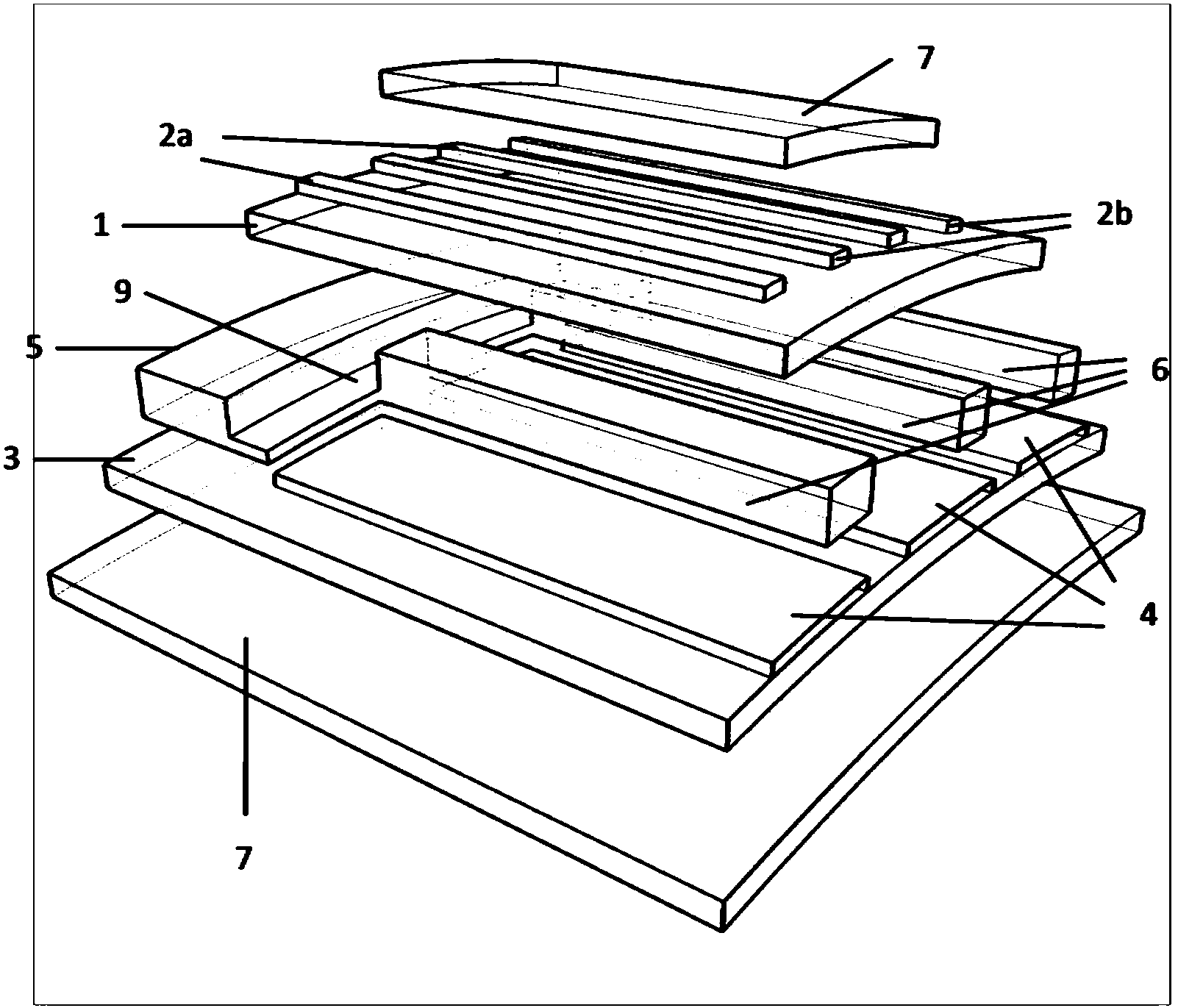
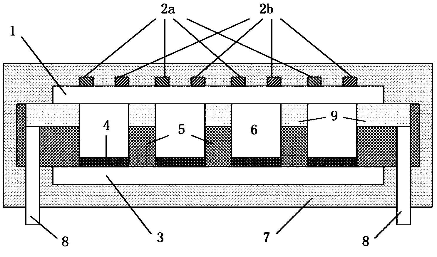
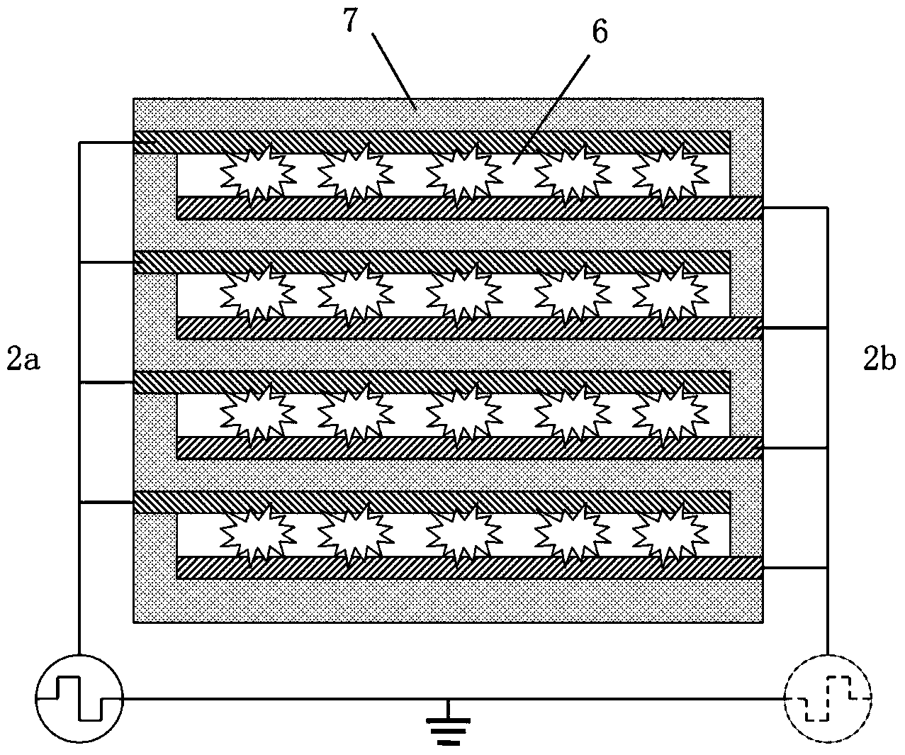
[0022] Such as figure 1 , 2 shown. Prepare electrode group 2a and electrode group 2b on front substrate glass 1, prepare phosphor layer 4 on rear substrate glass 3, add organic cavity layer 5 between described front substrate glass 1 and rear substrate glass 3, make organic The cavity 6 in the cavity layer 5 corresponds to the electrode group 2a and the electrode group 2b, and finally the front substrate glass 1 and the rear substrate glass 3 are covered with an organic polymer 7, and an exhaust pipe 8 is connected.

[0023] Microchannels 9 are prepared in the organic cavity layer 5, communicating with the cavity 6 and the exhaust pipe 8, so that all discharge spaces can be inflated and exhausted effectively. One or two exhaust pipes 8 can be used at the same time, and finally filled with Ar as the working gas, the pressure is 400-760torr, and then the exhaust pipe 8 is sealed.

[0024] It works as follows. It is divided into applying reverse positive and negative AC pulse...

Embodiment 2

[0026] The working gas in Example 1 is replaced by Xe (>20%) and Ne mixed gas, the Xe and Ne mixed gas discharges to emit vacuum ultraviolet light mainly at 147nm and 172nm, and then excites the fluorescent layer 4 to emit ultraviolet light.

Embodiment 3

[0028] The working gas in embodiment 1 is replaced by a pure Xe body, since the gas pressure is at 400-760 Torr, the three-body collision between the ground state Xe atom and the excited state Xe atom (such as ) increases, so that the gas discharge emits mainly 172nm vacuum ultraviolet light, and then excites the fluorescent layer 4 to emit ultraviolet light, which is emitted through the front substrate glass 1 and the organic polymer 7 .


PUM

PropertyMeasurementUnit
Thicknessaaaaaaaaaa
Thicknessaaaaaaaaaa
Thicknessaaaaaaaaaa

Abstract

A flexible flat panel ultraviolet light source includes a multilayer structure which is formed by an ultraviolet high-permeability organic polymer and an ultra-thin glass; the multilayer structure includes a front substrate, a back substrate, and an organic cavity layer positioned between the front substrate and the back substrate; edges around the front substrate, around the back substrate, and around the organic cavity layer are sealed; the front substrate is composed of the ultra-thin glass with the thickness of 30 to 100 mu m, the organic polymers with the thickness of 0.1 to 1 mm, and an electrode on the ultra-thin glass; the back substrate comprises the ultra-thin glass, the organic polymer, and a selective fluorescent powder coating layer on the ultra-thin glass; and the organic cavity layer positioned between the front substrate and the back substrate has the thickness of 10 mu m to 1 mm, and is internally provided with a discharge space which is formed by a cavity or passage with the width of 10 mu m to 5 mm. In the invention, the light source of the UVA, UVB, and UVC band radiation can be sent, and the air tightness and service life of the pure organic material device are increased.

Description

technical field [0001] The invention relates to an ultraviolet light source, in particular to a flexible flat ultraviolet light source made of both organic polymer and ultra-thin glass. Background technique [0002] Ultraviolet light source has important applications in environmental protection, energy, processing, lighting, medical treatment, etc., such as sterilization, laser excitation source, curing of photosensitive materials, material surface treatment, etching, degradation of pollutants, biomedical detection and diagnosis and treatment. Ultraviolet radiation refers to electromagnetic radiation with a wavelength between X-rays and visible light. Vacuum ultraviolet (VUV, 100nm ~ 200nm) four bands, the corresponding ultraviolet light source is called long wave, medium wave, short wave and vacuum ultraviolet light source respectively. For example, the narrow-band ultraviolet (NB-UVB) light source with a wavelength of about 312nm has been widely used in the medical indust...

Claims


Application Information

Patent Timeline
IPC IPC(8): H01J65/04H01J9/00
Inventor 匡文剑李青哈姆托勒胡凯
Owner 南京新港科技产业服务有限公司
Learn More