An ultra wide band quaternary array antenna apparatus used for a through-wall imaging radar

An ultra-wideband antenna and antenna arm technology, applied in the field of antenna devices, can solve the problems of limited signal amplitude, short radar detection distance, low antenna radiation efficiency, etc., and achieve simple feeding mode, strong adaptability, and simple operation and maintenance. Effect

Active Publication Date: 2014-03-26
INST OF ELECTRONICS CHINESE ACAD OF SCI
View PDF4 Cites 8 Cited by
  • Summary
  • Abstract
  • Description
  • Claims
  • Application Information

AI Technical Summary

Problems solved by technology

However, the radiation efficiency of this antenna is low, the amplitude of the signal g

Method used


Image

  • An ultra wide band quaternary array antenna apparatus used for a through-wall imaging radar
  • An ultra wide band quaternary array antenna apparatus used for a through-wall imaging radar
  • An ultra wide band quaternary array antenna apparatus used for a through-wall imaging radar

Examples


Embodiment Construction

[0022] In order to make the object, technical solution and advantages of the present invention clearer, the present invention will be described in further detail below in conjunction with specific embodiments and with reference to the accompanying drawings.

[0023] [Description of main component symbols]

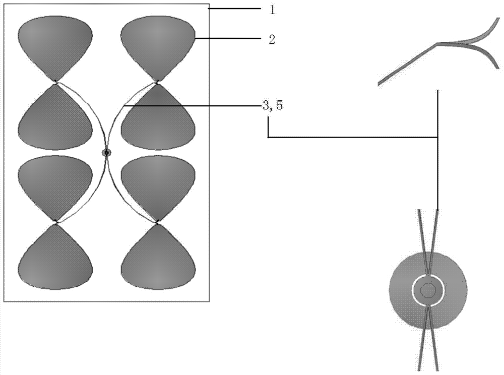
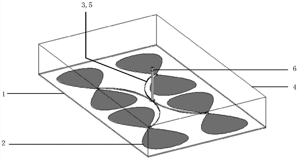
[0024] 1-FR4 dielectric board; 2-drop-shaped antenna arm;

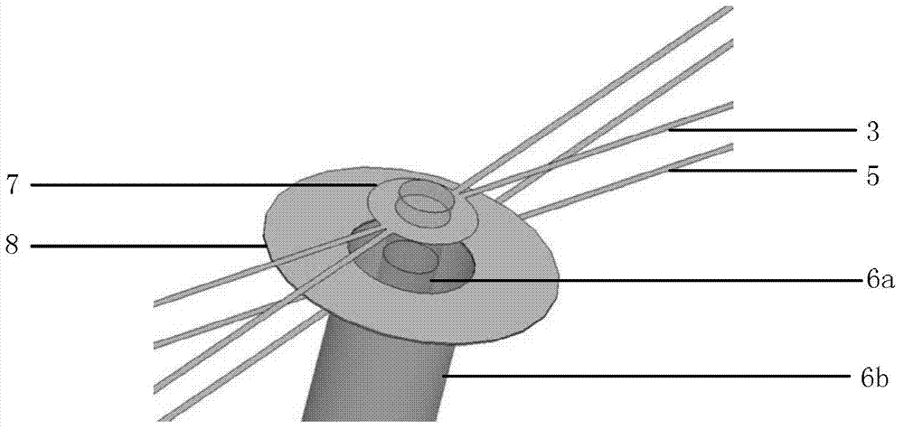
[0025] 3,5-parallel twin wires; 4-reflecting cavity;

[0026] 6-SMA connector;

[0027] 7-upper pad;

[0028] 8- lower pad;

[0029] figure 1 It is a schematic structural diagram of the ultra-wideband antenna device proposed by the present invention, figure 2 For the three-dimensional structural diagram of the ultra-wideband antenna device proposed by the present invention, as figure 1 , 2 As shown, the ultra-wideband antenna device includes: a dielectric unit 1, an antenna unit 2, a parallel dual-wire feed unit, a reflection cavity 4 and a connector 6, wherein:

[0030] In one embodiment of the present in...


PUM

PropertyMeasurementUnit
Thicknessaaaaaaaaaa

Abstract

The invention discloses an ultra wide band quaternary array antenna apparatus used for a through-wall imaging radar. The antenna apparatus comprises a medium unit, an antenna unit, a parallel double-line feed unit, a reflection cavity and a connector. The antenna unit is printed on the bottom surface of the medium unit. The antenna unit is composed of a plurality of water-drop-shaped antenna arms. The parallel double-line feed unit comprises a first parallel double-line and a second parallel double-line which are X-shaped and which are respectively arranged on the upper surface and the lower surface of the medium unit. Terminals, approaching the antenna arms, of the parallel double-line separate according to index gradual changes, and are respectively connected with the corresponding antenna arms. A central point of the two parallel double-lines are connected with the connector through upper and lower end bonding pads. The reflection cavity is fixed with the edge of the medium unit and covers the antenna unit. One end of the connector is connected with the parallel double-line feed unit. The other end penetrates outside the refection cavity via a through hole in the middle of the reflection cavity and is fixed on the reflection cavity. The antenna apparatus of the present invention can be directly connected with a transmit-receive module through the connector, and the antenna apparatus has relatively good orientated radiation capability and broadband characteristics.

Description

technical field [0001] The present invention relates to an antenna arrangement for a through-wall imaging radar system. Background technique [0002] Through-wall imaging technology is a fast imaging method that does not need to destroy the wall, has good resolution and penetration depth, and can perform non-invasive detection and imaging of targets hidden behind walls. In recent years, through-wall imaging detection technology has received more and more attention, especially in the fields of anti-terrorism, technical investigation, military, search and rescue, etc., which has great application value. [0003] my country's research on through-wall imaging technology started relatively late. At present, some domestic universities and scientific research institutions have carried out some useful explorations in this field and are basically in the stage of laboratory prototypes. [0004] At present, the through-wall imaging radar systems that are widely used in China are basic...

Claims


Application Information

Patent Timeline
IPC IPC(8): H01Q1/38H01Q1/50H01Q19/10H01Q21/00
Inventor 纪奕才邵金进陈洁方广有阴和俊
Owner INST OF ELECTRONICS CHINESE ACAD OF SCI
Why Eureka
Try Eureka