Vacuum light-condensing through high-temperature heat collecting pipe

A heat collecting tube and high temperature technology, which is applied in the field of vacuum concentrating direct high temperature heat collecting tubes, can solve the problems of difficult processing, complicated processing methods, breakage, etc., and achieves simple and easy system design, ensures vacuum heat insulation effect, and improves light transmittance. Effect

Inactive Publication Date: 2014-04-02
NANJING CHENGYUAN SOLAR HEATING +1
View PDF7 Cites 5 Cited by
  • Summary
  • Abstract
  • Description
  • Claims
  • Application Information

AI Technical Summary

Problems solved by technology

[0003] CN102278832A Chinese patent document discloses a medium-high temperature heat collecting tube for internal concentrating solar energy and its manufacturing method. It is to position the reflector 3 in the vacuum chamber through the elastic bracket 8, and the heat-absorbing tube adopts the metal sleeve 5, and the structure is relatively Complicated and difficult to process, although they have high thermal efficiency in theory, we have found in practice that because the inner layer of the vacuum cavity in the medium-high temperature heat collecting tube is in contact with the high-temperature area, and the outer layer is located in the external natural space, during the working process of the product , the temperature difference between the inner and outer layers is generally more than 4-5 times, the inner and outer glass of the vacuum chamber is very easy to form stress concentration at their junction, so that the junction of the inner and outer glass is damaged, thus losing the ability to prevent the inner high temperature area from flowing through the vacuum. Technical advantage of externally diffused heat
[0004] CN202521925U Chinese patent document discloses a kind of internal concentrating light-bearing pressurized solar energy medium and high temperature heat collecting tube, mainly for the complex processing method that the reflecting plate is positioned in the vacuum cavity through the elastic bracket, and the reflective plate is moved to the outside of the vacuum cavity by glass In the sealed cavity constructed by the outer cover tube, this structure is also not solved. Because the temperature difference between the inner and outer layers of the medium and high temperature heat collecting tube is generally more than 4-5 times, it is very easy to form stress concentration at the junction of the inner and outer glass of the vacuum tube, making the inner and outer glass The technical problem of damage to the joint part, and the practical problem that the heat-absorbing tube adopts a metal sleeve, the structure is relatively complicated, and the processing is difficult

Method used


Image

  • Vacuum light-condensing through high-temperature heat collecting pipe
  • Vacuum light-condensing through high-temperature heat collecting pipe

Examples


Embodiment Construction

[0016] The accompanying drawings disclose the specific structures of the embodiments of the present invention without limitation, and the present invention will be further described below in conjunction with the accompanying drawings.

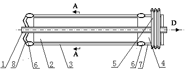
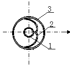
[0017] Depend on figure 1 and figure 2 It can be seen that the present invention includes an outer tube 3, an inner tube and a light-concentrating reflector 2, the outer tube 3 is a glass tube, the inner tube coaxially arranged is a heat-absorbing heat-conducting tube 1, and one end of the outer tube 3 is provided with an axially deformable metal end cap 8, and the other end is provided with a valve-capable metal tube 7 head, the metal end cap 8 and the valve-capable metal tube 7 are sealed with the end of the outer tube 3 to form a vacuum sealed cavity 4, suction Both ends of the heat pipe 1 protrude from the vacuum sealed cavity 4; The metal end cap 8 and the valveable metal tube 7 in the head 5 are solidified with the end of the outer tub...


PUM


Abstract

The invention relates to a vacuum light-condensing through high-temperature heat collecting pipe which comprises an outer pipe, an inner pipe and a light-condensing reflector. The vacuum light-condensing through high-temperature heat collecting pipe is characterized in that the outer pipe is a glass pipe, the coaxially-arranged inner pipe is a heat-absorbing heat conducting pipe, a metal end cap capable of axially deforming is arranged at one end of the outer pipe, a sealing head containing a valve-enabling metal pipe is arranged at the other end of the outer pipe, the metal end cap and the sealing head are hermetically connected with the end portion of the outer pipe to form a vacuum sealed cavity, two ends of the heat-absorbing heat conducting pipe extend out of the vacuum sealed cavity, the light-condensing reflector is positioned in the vacuum sealed cavity, and a focal point of the light-condensing reflector is positioned on the central axis of the heat-absorbing heat conducting pipe.

Description

technical field [0001] The invention relates to a high-temperature heat collecting tube, in particular to a vacuum concentrating straight-through high-temperature heat collecting tube. Background technique [0002] Mechanistically, heat loss can be explained in three ways: gas convection, material conduction and radiation. The heat collecting tube is a key component of a solar heat collector. Generally, there are composite glass heat collecting tubes, metal heat collecting tubes and metal vacuum heat collecting tubes composed of glass and metal tubes. [0003] CN102278832A Chinese patent document discloses a medium-high temperature heat collecting tube for internal concentrating solar energy and its manufacturing method. It is to position the reflector 3 in the vacuum chamber through the elastic bracket 8, and the heat-absorbing tube adopts the metal sleeve 5, and the structure is relatively Complicated and difficult to process, although they have high thermal efficiency in...

Claims


Application Information

Patent Timeline
Patent Type & Authority Applications(China)
IPC IPC(8): F24J2/46F24J2/05F24J2/24F24J2/10F24S10/40F24S10/70F24S23/70
CPCY02E10/44
Inventor 朱雷
Owner NANJING CHENGYUAN SOLAR HEATING
Why Eureka
Try Eureka