Current detection device and method

A current detection device and current technology, applied in the direction of controlling electromechanical transmission devices, electrical components, controlling generators, etc., can solve the problems of expensive Hall sensors, large size and high cost of Hall sensors, and achieve easy printed board layout. Realize, save hardware cost, and have the effect of good cost advantage

Active Publication Date: 2014-04-02
SHENZHEN HOPEWIND ELECTRIC CO LTD
View PDF5 Cites 16 Cited by
  • Summary
  • Abstract
  • Description
  • Claims
  • Application Information

AI Technical Summary

Problems solved by technology

[0003] However, because the Hall sensor is usually expensive, in the actual industrial implementation, it will greatly increase the cost of the low-voltage electric vehicle driver, and, because the Hall sensor usually has a large volume, it is suitable for those with limited printed board area. resource is not a small bottleneck for low-voltage electric vehicle drives
[0004] In addition to the Hall sensor, for the output current detection of the electric vehicle driver, the three-resistor current detection method, the dual-resistor current sampling method, and the single-resistor current sampling method are also used in the prior art, but the common disadvantages of these methods are : They all need to use precision resistors, also known as shunts, which undoubtedly have a high cost; and are only suitable for applications with relatively small output currents. This is because t

Method used


Image

  • Current detection device and method
  • Current detection device and method
  • Current detection device and method

Examples


Example Embodiment

[0066] The technical scheme of the present invention will be described in further detail below in conjunction with the accompanying drawings and specific examples, so that those skilled in the art can better understand the present invention and implement it, but the examples given are not intended to limit the present invention .

[0067] The main problem to be solved by the invention is to provide a novel current detection device and method for the problem that the current general frequency converter current sampling method is difficult to apply to the low-voltage electric vehicle driver.
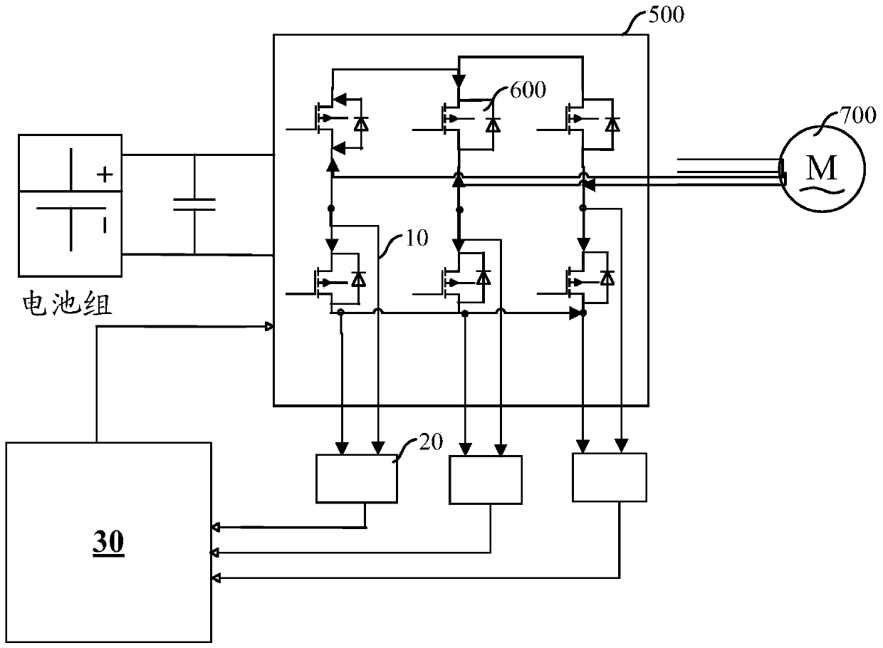
[0068] The core idea of ​​the present invention to solve the above-mentioned technical problems is to use the conduction voltage drop of the MOSFET to perform current sampling and calculation to obtain the current value of the bridge arm, and then perform current reconstruction according to the sector of the space voltage vector PWM (SVPWM) to obtain the phase of the current. current. The...


PUM


Abstract

The invention discloses current detection device and method. The device comprises a voltage detection circuit, an operational amplifier circuit and a microprocessor, wherein the voltage detection circuit is used for detecting voltage at two ends of each of at least three metal oxide semiconductor field effect transistors (MOSFETs) in a power inverter circuit of a driver; the operational amplifier circuit is used for respectively obtaining breakover current of a corresponding bridge arm of the power inverter circuit according to the voltage and the conduction resistance of each MOSFET and also for providing the sampled current obtained after amplification treatment to the microprocessor; the microprocessor is used for carrying out analog-to-digital conversion on the sampled current and then carrying out current reconstruction on the sampled current subjected to analog-to-digital conversion according to the space vector pulse width modulation (SVPWM) sector, so as to obtain at least three phases of output phase current of the driver. By adopting the current detection device and method, the current is detected by an inherent inverse MOSFET bridge arm, so that the hardware cost is saved, meanwhile, the same performance as the current sensor can be achieved, and the detection device has excellent cost advantage for a low-voltage vehicle driver and also has the beneficial effects of small power consumption, easy accomplishment of printed board layout and the like.

Description

technical field [0001] The present invention relates to the technical field of motor control, in particular to a current detection device and method for a low-voltage electric vehicle driver. Background technique [0002] Knownly, for the output current detection of the electric vehicle driver, the method currently adopted is to use the Hall sensor to detect the two-phase output current, and the third phase current is obtained by vector sum. This method has better current sampling accuracy, And it is also relatively simple in terms of software processing and implementation. [0003] However, because the Hall sensor is usually expensive, in the actual industrial implementation, it will greatly increase the cost of the low-voltage electric vehicle driver, and, because the Hall sensor usually has a large volume, it is suitable for those with limited printed board area. It is not a small bottleneck for low-voltage electric vehicle drives with resources. [0004] In addition to...

Claims


Application Information

Patent Timeline
IPC IPC(8): H02P21/13
Inventor 徐中领
Owner SHENZHEN HOPEWIND ELECTRIC CO LTD
Why Eureka
Try Eureka