
Linear LED (light-emitting diode) driving circuit based on alternating-current power supply

A technology of LED drive and alternating current, applied in the direction of electric lamp circuit layout, electric light source, light source, etc., can solve problems affecting vision health, changes in light and shade of lamps, and changes in the average luminous intensity of LEDs, etc., to achieve improved power conversion efficiency and constant average power Effect

Inactive Publication Date: 2014-04-02
UNIV OF ELECTRONICS SCI & TECH OF CHINA
View PDF2 Cites 6 Cited by
  • Summary
  • Abstract
  • Description
  • Claims
  • Application Information

AI Technical Summary

Problems solved by technology

There are also defects in the way of using multi-branch LEDs in series. The number of LED lamp beads changes with the change of the power supply voltage, which will lead to changes in the average luminous intensity of the LEDs and changes in the brightness of the lamps, which will affect vision health in the long run

Method used


Image

  • Linear LED (light-emitting diode) driving circuit based on alternating-current power supply
  • Linear LED (light-emitting diode) driving circuit based on alternating-current power supply
  • Linear LED (light-emitting diode) driving circuit based on alternating-current power supply

Examples


Embodiment 1

[0035] Such as Figure 7 As shown, the LED module in this example includes 4 LED branches, and each LED branch includes 3 LED lamp beads. All comparators use operational amplifiers. The specific working principle is:

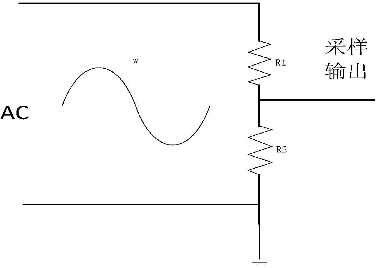
[0036] The AC sine wave AC is rectified by the rectifier bridge to become DC. When the voltage is zero, the four LED modules have no current, the current flowing through the sampling resistor Rs is zero, the voltage on the sampling resistor is zero, and the voltage fed back to the negative input terminals of the four operational amplifiers is zero. In the voltage divider module set by the sampling circuit, the sampling voltage is 0, and the outputs of M1, M2, M3, and M4 are all low level. M1, M2, M3, and M4 are respectively connected to the enabling terminals of the operational amplifiers from branch one to branch four, forcing the output of the operational amplifier to be low level, and the four MOS transistors M1M2...M4 are in the cut-off state. Duration is ...

Embodiment 2

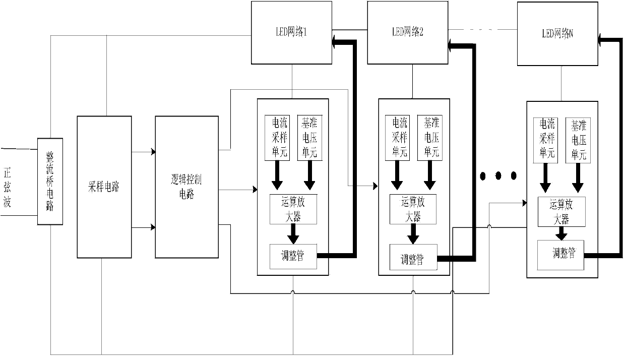
[0061] Such as Figure 8 As shown, the basic structure and principle of this example are the same as those of Example 1. The difference is that in this example, the reference voltage input by the non-inverting terminal of the operational amplifier is set to be equal, and the clamping effect of the operational amplifier is used to ensure the constant current of the LED lamp bead.

[0062] Such as Figure 9 As shown, it is a low-offset high-gain operational amplifier with an enable terminal in the present invention, which can be used as a comparator.

[0063] Such as Figure 10 Shown is the waveform diagram of the rectified waveform and the comparative voltage in the present invention.


PUM


Abstract

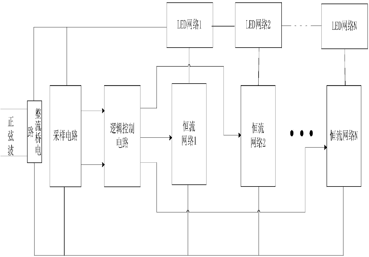
The invention relates to an electronic circuit technology and particularly relates to a linear LED (light-emitting diode) driving circuit based on alternating-current power supply. The linear LED driving circuit comprises a rectifier bridge circuit and a plurality of LED modules and is characterized by further comprising a sampling circuit, a logic control circuit and a plurality of constant-current modules, wherein the rectifier bridge circuit and the sampling circuit, and the LED modules and the constant-current modules are connected, the sampling circuit is connected with the logic control circuit, the logic control circuit is respectively connected with each constant-current module, the number of the constant-current modules is the same with that of the LED modules, and the constant-current modules are sequentially correspondingly connected with the LED modules. The linear LED driving circuit provided by the invention has the beneficial effects of effectively improving electric energy conversation efficiency, realizing constant current of the LED and constant average power of the LED and regulating the number of the LED and setting the power of LED lamps according to demands. The linear LED driving circuit provided by the invention is particularly suitable for linear LED driving.

Description

technical field [0001] The invention relates to electronic circuit technology, in particular to a linear LED driving circuit based on alternating current power supply. Background technique [0002] Currently, in the field of LED driving circuit design, LED driving methods include linear driving and switching power supply driving. As a traditional driving method, switching power supply drive has many disadvantages. In contrast, the linear drive method has the advantages of simple structure and low electromagnetic interference EMI, but it also has problems such as low efficiency and poor regulation. In the case of only one LED branch, the efficiency is low due to the large voltage variation range in the case of AC power supply. Therefore, the method of connecting multi-branch LEDs in series is adopted, and different numbers of LEDs are connected in series with the power supply system according to the change of the supply voltage, so as to improve the efficiency. There are al...

Claims


Application Information

Patent Timeline
Patent Type & Authority Applications(China)
IPC IPC(8): H05B37/02
Inventor 李泽宏张建刚李蜀一刘建弋才敏肖诩汪榕
Owner UNIV OF ELECTRONICS SCI & TECH OF CHINA
Learn More