
Split self-circulation chemical synthesizer

A chemical synthesis and self-circulation technology, applied in chemical instruments and methods, organic chemistry, chemical/physical processes, etc., can solve the problems of large power consumption and achieve the effects of overcoming large power consumption, reducing power consumption, and easy manufacturing

Inactive Publication Date: 2014-04-09
李建梅
View PDF2 Cites 0 Cited by
  • Summary
  • Abstract
  • Description
  • Claims
  • Application Information

AI Technical Summary

Problems solved by technology

[0004] The purpose of the present invention is to overcome the disadvantage that the existing chemical synthesis equipment needs to repeatedly cycle and compress the raw material gas and consume a large amount of electric energy, and design a split type self-circulating chemical synthesizer, which automatically circulates to carry out the chemical synthesis reaction by the chemical synthesizer itself. The raw material gas can be completely synthesized into the target product only through one compression, so as to greatly reduce power consumption and improve catalytic efficiency, and realize energy saving and reduction in the production of synthetic ammonia, methanol, dimethyl ether and other production processes that require chemical synthesis. Row

Method used


Image

  • Split self-circulation chemical synthesizer

Examples


Embodiment Construction

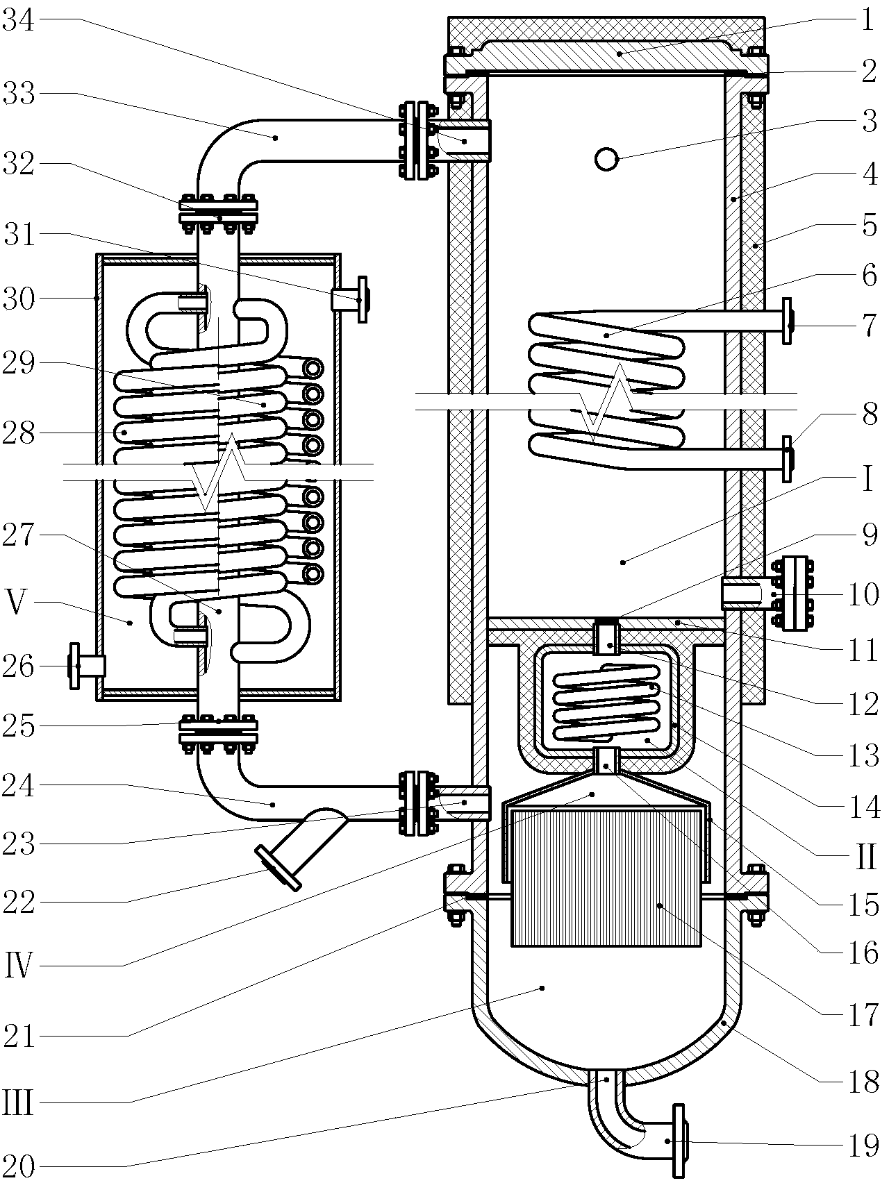
[0017] In the embodiment shown in the accompanying drawings, the split type self-circulating chemical synthesizer constitutes a self-circulating system by a heat exchanger and a reactor, wherein the heat exchanger is composed of a downcomer and a shell (30), and the inner space of the shell (30) Constitute the cooling chamber (Ⅴ), the downpipe is set in the cooling chamber (Ⅴ), the upper nozzle of the downpipe passes through the top of the cooling chamber (Ⅴ) and connects to the input interface a (32), the lower end of the downpipe The mouth passes through the bottom of the cooling chamber (Ⅴ) and is connected to the output interface a (25), the lower part of the cooling chamber (Ⅴ) has an input interface b (26) connected, and the upper part of the cooling chamber (Ⅴ) has an output interface b (31) connected; the reactor consists of an upper end (1), a wall (4), a lower end (18), a gas-liquid separator (17), a gas collection hood (15) and a preheating chamber (II), The upper e...


PUM


Abstract

The invention discloses a split self-circulation chemical synthesizer and relates to a chemical synthesis reactor. A heat exchanger and a reactor form a self-circulation system, wherein the heat exchanger consists of a down pipe and a shell; a cooling chamber is formed by an inner space of the shell; the down pipe is arranged in the cooling chamber; the reactor consists of an upper end head, a wall body, a lower end head, a gas-liquid separator, a gas-collecting hood and a preheating chamber; the upper end head is arranged at an upper opening of the wall body; the lower end head is arranged at a lower opening of the wall body; the upper end head and an inner space defined by a middle section and an upper section of the wall body form a reaction chamber; the lower end head and an inner space defined by a lower section of the wall body form a gas-liquid separation chamber; a clapboard is arranged between the reaction chamber and the gas-liquid separation chamber for isolating; a circulating gas input opening is formed in the clapboard. The automatic circulation is realized by the chemical synthesizer under inner isobaric conditions, and a target product is timely separated, so that raw material gas can be totally synthesized into the target product through one-step compression only, the power consumption is greatly reduced, and the catalytic efficiency is improved.

Description

technical field [0001] The invention relates to a chemical equipment, in particular to a chemical synthesis reactor. Background technique [0002] In the presence of catalysts, most chemical synthesis reactions are reversible reactions. When the target product reaches a certain concentration, it will be in equilibrium, and the reaction will no longer proceed in the direction of synthesizing the target product. In the production process of the compound reaction, in order to make the reaction continue to the direction of the target product, the mixed product must be output from the synthesis reactor and new raw material gas must be added to the synthesis reactor to make the target in the synthesis reactor After the product concentration is reduced and the balance is broken, the combination reaction continues. After the mixed product is output from the synthesis reactor, the unreacted gas is separated through the separation equipment, and then the unreacted gas is returned to t...

Claims


Application Information

Patent Timeline
Patent Type & Authority Applications(China)
IPC IPC(8): B01J8/02C01C1/04F28D7/00C07C31/04C07C29/152C07C43/04C07C41/01
Inventor 周开根
Owner 李建梅
Learn More