Thermal management system of power battery

A technology of thermal management system and power battery, applied in the field of thermal management system, can solve problems such as battery thermal management system runaway, battery short circuit, temperature difference, etc., to increase the ambient temperature range, fast heating and cooling speed, and reduce the overall burden Effect

Active Publication Date: 2014-04-09
CHINA AUTOMOTIVE BATTERY RES INST CO LTD
View PDF4 Cites 98 Cited by
  • Summary
  • Abstract
  • Description
  • Claims
  • Application Information

AI Technical Summary

Problems solved by technology

[0004] Although the above battery thermal management system can achieve heat dissipation effect, the design has the following disadvantages: when the battery temperature fluctuates rapidly in the fan cooling mode, it is difficult to adjust the temperature balance in a short time, and due to the wind resistance of various places in the battery box Different battery modules lead to uneven heat dissipation and large temperature differences, and it is easy for dust to enter the battery box; the use of automotive air conditioners to cool and heat batteries relies heavily on automotive air conditioners, and the battery thermal management system cannot be independent When the vehicle’s air conditioner fails, it may cause the battery thermal management system to run out of control; the liquid circulation is used to

Method used


Image

  • Thermal management system of power battery
  • Thermal management system of power battery
  • Thermal management system of power battery

Examples


Embodiment 1

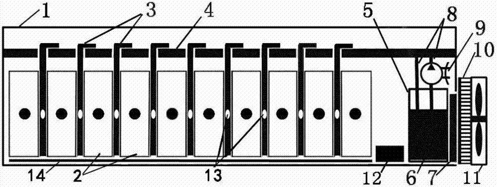
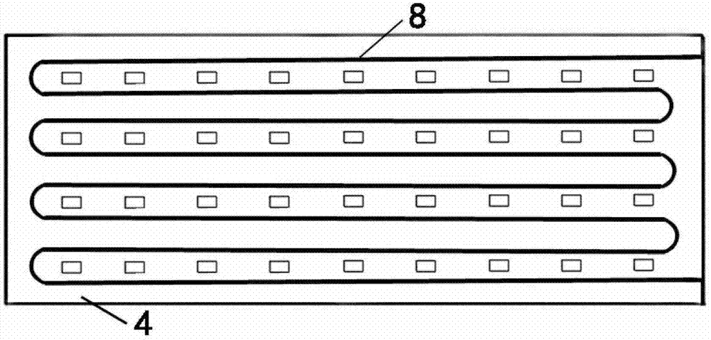
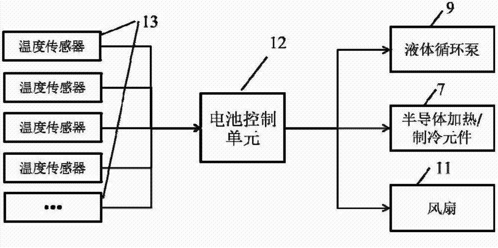
[0031] Such as figure 1 The power battery thermal management system shown is mainly composed of battery box 1, heat pipe 3, liquid flow plate 4, liquid tank 5, semiconductor heating / cooling element 7, liquid circulation pump 9, battery control unit 12, temperature sensor 13, radiator 10. The fan 11 is composed of the radiator 10 and the fan 11 installed outside the battery box 1. The radiator 10 is an aluminum alloy finned radiator, which is mainly composed of a heat conducting surface and a heat sink. The radiator 10 is installed in the battery box. On the outside, the fan 11 is installed at the best position that can be aligned with the outside of the heat sink; the heat pipe 3, the liquid flow plate 4, the liquid tank 5, the semiconductor heating / cooling element 7, the liquid circulation pump 9, the battery control unit 12 and the temperature sensor 13 Fixed in the battery box 1, battery modules 2 arranged in parallel are also installed in the battery box 1, and two heat pi...

Embodiment 2

[0036] As in the power battery thermal management system shown in Example 1, when the battery module 2 in the battery box 1 is small in size and generates less heat, or the selected heat pipe 3 has a strong heat transfer capability, under the condition that other components remain unchanged , adjust the number of heat pipes 3 inserted into the gaps between each adjacent battery module 2 , and a better heat transfer effect can be achieved by inserting one heat pipe 3 .

Embodiment 3

[0038] For the power battery thermal management system shown in Example 1, when the battery module 2 in the battery box 1 is large in size and generates a lot of heat, or the heat transfer capacity of the selected heat pipe 3 is weak, the other structural components remain unchanged. In some cases, adjust the number of heat pipes 3 inserted into the gap between each adjacent battery module 2, and insert four heat pipes 3 at even intervals to maintain a better heat transfer effect.


PUM


Abstract

The invention relates to a thermal management system of a power battery, and belongs to a component of a battery management system. The thermal management system of the power battery mainly consists of a battery box, a heat pipe, a liquid flow pipe, a liquid box, a semiconductor heating/refrigerating element, a liquid circulating pump, a battery control unit, a temperature sensor, a radiator and a fan. The radiator and the fan are installed outside the battery box, the battery box, the heat pipe, the liquid flow pipe, the liquid box, the semiconductor heating/refrigerating element, the liquid circulating pump, the battery control unit and the temperature sensor are installed in the battery box and organically combined with a battery module. The heat pipe is inserted into the battery module. The heat pipe is compactly attached to the battery module and the liquid flow plate above the battery module. The liquid flow plate is internally provided with a liquid circulating pipeline connected with the liquid circulating pump which is further connected with the liquid box filled with a circulating liquid. The semiconductor heating/refrigerating element is contacted with the liquid box and attached to the radiator. The battery box is further provided with the temperature sensor connected with battery control unit which controls the liquid circulating pump, the semiconductor heating/refrigerating element and the fan to work. The thermal management system of the power battery provided by the utility model is reasonable in structure and can quickly heat and cool.

Description

technical field [0001] The invention relates to a thermal management system of a power battery, which belongs to a component of the power battery management system. Background technique [0002] At present, the world's energy crisis and environmental pollution are becoming more and more serious. The disposable energy is decreasing and the price of crude oil is rising. All countries are stepping up the research and development of new energy vehicles. The future focus on the development of transportation. The power battery is the energy carrier driven by pure electric vehicles and hybrid vehicles. In order to meet the requirements of fast charging and driving range, as well as the vehicle performance under climbing, acceleration and other working conditions, the power battery must have high power output and large capacity. In order to ensure the high capacity and high power of the power battery, a large number of single power batteries are usually connected in parallel or in...

Claims


Application Information

Patent Timeline
IPC IPC(8): H01M10/613H01M10/615H01M10/617H01M10/625H01M10/6572H01M10/6552H01M10/635H01M2/10H01M50/24H01M50/244H01M50/289
CPCH01M2220/20H01M50/20Y02E60/10
Inventor 付垚唐海波卢世刚胡博薛轶邹春龙
Owner CHINA AUTOMOTIVE BATTERY RES INST CO LTD
Why Eureka
Try Eureka