Electric locomotive electronic mutual inductor and application method thereof

A technology of electronic transformers and voltage transformers, which is applied in the direction of electrical components, output power conversion devices, and conversion equipment that can be converted to direct current without intermediate conversion, and can solve the problem of inability to identify various parameter values ​​of electronic transformers The accuracy and accuracy meet the international or national measurement requirements, without considering the use of immature technology, affecting the safe operation of the transmission network and other issues, achieving strong stability and anti-interference, avoiding damage to the output transformer, and wide application range

Active Publication Date: 2014-04-09
株洲中车轨道交通装备有限公司
View PDF1 Cites 11 Cited by
  • Summary
  • Abstract
  • Description
  • Claims
  • Application Information

AI Technical Summary

Problems solved by technology

[0005] 1. The corresponding international or national standards for civilian electronic transformers have just been issued, but there are no corresponding international or national or industry standards for electronic transformers on railway electric locomotives, and it is impossible to identify the various parameter values ​​​​of electronic transformers and Accuracy meets international or national metrology requirements
[0006] 2. In the past, technologies such as electronic voltage transformers, especially high-voltage signal sampling and high-voltage isolation circuit processing (including its voltage-dividing sampling materials and over-voltage protection devices) were still in the exploratory and experimental stage in terms of safety and reliability in civil power systems. It directly affects the safe operation of subsequent circuits and even the entire transmission network. In the railway transportation system all over the world, the safe operation of electric locomotives is the guarantee of the safety of passengers and property. As far as the overall design principles of electric locomotives are concerned, immature use is not considered. technical
[0008] 4. In the past, electric locomotives in my country used traditional electromagnetic voltage transformers to measure the voltage of the primary power grid. The failure rate was not too high when the AC / DC electric locomotives were not used in large quantities in the railway transportation system.

Method used


Image

  • Electric locomotive electronic mutual inductor and application method thereof
  • Electric locomotive electronic mutual inductor and application method thereof
  • Electric locomotive electronic mutual inductor and application method thereof

Examples


Embodiment 1

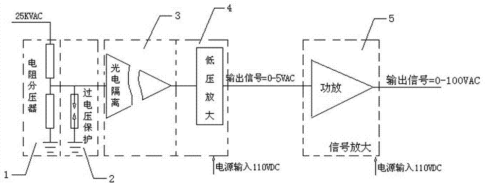
[0057] The product of embodiment 1 is designed to replace the high-voltage electromagnetic transformer on the non-network control electric locomotive, and its structure is as follows Figure 4 As shown, a dual-circuit redundant design is adopted. In the figure, A is the original electronic voltage transformer, and B is the backup electronic voltage transformer, which is switched by the transfer switch 10. Its external interface is connected with the electromagnetic high-voltage mutual inductor installed on the locomotive. The device is the same, which is beneficial to replace the original electromagnetic high-voltage transformer of the electric locomotive, and reduces the difficulty of replacing the electronic high-voltage transformer of the present invention. The specific work of each circuit module is as follows:

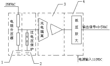
[0058] Resistor voltage divider circuit: The voltage divider resistor is mainly used to step down and sample the network voltage input by the locomotive, so that ...

Embodiment 2

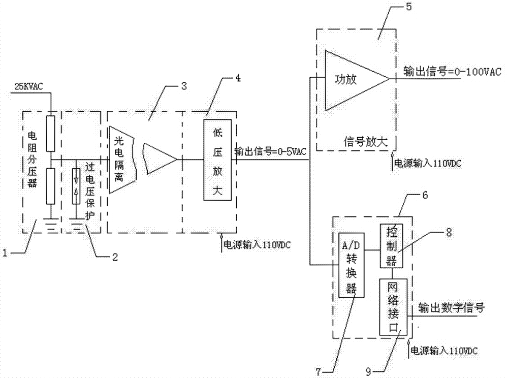
[0068]The product of Example 2 is designed for network-controlled electric locomotives. According to the requirements of different locomotive communication interfaces, corresponding communication protocols (such as: MVB train multi-function communication protocol) are used for software programming to realize digital signals and locomotive network control systems. communication, such as Figure 5 As shown, the electronic voltage transformer adopts a double-circuit redundant design. In the figure, C is the original electronic voltage transformer, and D is the standby electronic voltage transformer. Switching is performed through the transfer switch 11. Photoelectric isolation and signal conditioning, signal A / D conversion, and network communication interface part realize the circuit function. The specific work of each circuit module is as follows:

[0069] Resistor voltage divider circuit: The voltage divider resistor is mainly used to step down and sample the network voltage i...


PUM


Abstract

The invention discloses an electric locomotive electronic mutual inductor and an application method thereof. The mutual inductor comprises a voltage dividing circuit, an overvoltage protection circuit, a high voltage side photoelectric isolation processing unit circuit and a low voltage amplification circuit, wherein the output end of the voltage dividing circuit is connected with the input ends of the overvoltage protection circuit and the high voltage side photoelectric isolation processing unit circuit; the overvoltage protection circuit is grounded; the output end of the high voltage side photoelectric isolation processing unit circuit is connected with the low voltage amplification circuit; the voltage dividing circuit draws electricity from a high voltage contact network and directly divides high voltage into low voltage AC signals, and the voltage, after photoelectric isolation and signal reduction processing by the high voltage side photoelectric isolation processing unit circuit, is also converted into the low voltage AC signals for use of a rear-stage low voltage amplification circuit; and the low voltage amplification circuit is used for shaping of photoelectric isolation signals and at the same time performing feedback on the forward output of a linear optical coupler to enable the conversion precision of the linear optical coupler to meet design requirements. The mutual inductor and the application method, provided by the invention, have the advantages of small size, light weight, loss power consumption, good stability, high safety performance and the like.

Description

technical field [0001] The invention relates to a device for measuring grid voltage, in particular to an outdoor electronic voltage transformer for electric locomotives and its application on electric locomotives. Background technique [0002] As we all know, an electric locomotive obtains 25kV, 50Hz single-phase power frequency AC power from the catenary, and the high voltage of the catenary is sent to the traction transformer inside the locomotive through the pantograph, main circuit breaker, and high-voltage current transformer, while the high-voltage voltage transformer on the locomotive is mainly Realize catenary voltage measurement, power calculation and protection functions. The high-voltage voltage transformer (generally 25kV / 100V or 25kV / 150V) is connected in parallel to the 25kV high-voltage busbar on the roof, and the 25kV is reduced to 100V (or 150V) to provide the voltage source for the display of the locomotive network voltage meter and the locomotive watt-hour...

Claims


Application Information

Patent Timeline
Patent Type & Authority Applications(China)
IPC IPC(8): H02M5/04H02M1/32
Inventor 张光群徐宗祥索建国邱子荣袁赞江邹大江
Owner 株洲中车轨道交通装备有限公司
Why Eureka
Try Eureka