Deep hole machining ejector drill

A jet-suction drilling and deep hole technology, applied in metal processing equipment, drilling/drilling equipment, repairing and other directions, can solve the problems of uncontrollable water flow in the inner hole, affecting the cooling of the front-end drill bit, and short tool life, etc. To achieve the effect of easy iron filings discharge, ingenious structure and improved quality

Active Publication Date: 2014-04-23
NINGBO RONGKE MAITE NC TOOLS
View PDF5 Cites 3 Cited by
  • Summary
  • Abstract
  • Description
  • Claims
  • Application Information

AI Technical Summary

Problems solved by technology

In addition, 1 / 3 of the coolant is sprayed toward the back of the inner hole at the diversion point. Since the nozzle is small, the injection effect generated when the cutting fluid is sprayed out can make the inner hole form a negative pressure zone, so that a pressure difference is formed between the front and rear ends of the inner hole. , produce a certain suction force, accelerate the coolant with iron chips at the front to flow backward, and discharge the chips. In actual production, there are several problems: 1. When machining deep holes, due to chip removal, cooling and other reasons, the tool is used The service life is short, and the blunt blade can only be scrapped as a whole, which wastes resources and increases the cost; 2. Due to the angle and structure of the drill bit, the iron filings are not broken into needles or finely divided, and it is easy to block the inner hole. 3. The inner hole The water flow cannot be controlled, and sometimes the pressure is too high, and the water is pumped too fast, which will affect the cooling of the front drill bit and cause the drill bit to be scrapped

Method used


Image

  • Deep hole machining ejector drill
  • Deep hole machining ejector drill
  • Deep hole machining ejector drill

Examples


Embodiment Construction

[0023] The present invention will be further explained below in conjunction with the accompanying drawings and specific embodiments. It should be understood that the following specific embodiments are only used to illustrate the present invention and are not intended to limit the scope of the present invention. It should be noted that the words "front", "rear", "left", "right", "upper" and "lower" used in the following description refer to the directions in the drawings, and the words "inner" and "outer ” refer to directions towards or away from the geometric center of a particular part, respectively.

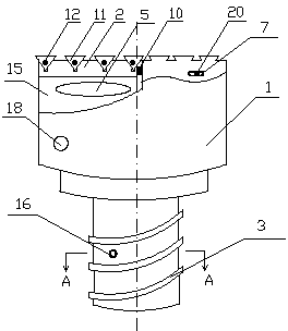
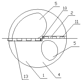
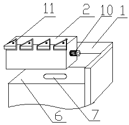
[0024] As shown in the figure, an ejector drill for deep hole processing according to the present invention includes a drill body 1, two tool holders 2 and a hollow connecting thread 3, the drill body 1 is in the shape of a fan blade 4, and the hollow interior is Chip outlet channel 5, the number of the blades 4 is 2, the blades 4 are evenly distributed around the central axis ...


PUM


Abstract

The invention discloses a deep hole machining ejector drill. The deep hole machining ejector drill comprises a drill body, two tool chucks and a hollow connecting thread, and is skilful in structure. Tool bits are overlapped in a staggered way along the central line of a lower end face, two tool chuck mounting grooves are unequal in lengths, and the length of a longer tool chuck mounting groove is 0.5-1 millimeter larger than the radius of the drill body. During working, cutting edges cover an entire machining surface, and the machining surface is flat. Since a plurality of cutting edges are adopted for cutting, reliable chip breaking is ensured, and scrap iron is fine and easy to discharge and is prevented from blocking. Acting force produced in a cutting process is shared by a plurality of tool bits, thereby prolonging the service lives of the tool bits. The aim of controlling the water current is fulfilled by using a current limiting plate, cutting edges can be cooled fully, and the service lives of the tool bits are prolonged. Since cutting edges of the drill bits are replaced by easily-replaceable parts such as tool chucks and tool bits, fittings can be replaced, tool bodies are protected, and the production cost is reduced. Since drill body is provided with two vanes which are uniformly distributed around the central axis of the drill body, radial force acting on two symmetrical cutting edges in a machining process is counteracted, the drill body is prevented from vibrating, the surface accuracy of machined holes is increased, and the quality of a machined product is enhanced.

Description

technical field [0001] The invention belongs to the technical field of deep hole processing, and in particular relates to an ejector-suction drill for deep hole processing. Background technique [0002] Now in the machinery factory, the length: diameter > 5 holes are called deep holes, and the deep holes with a diameter greater than 25mm are generally processed with an ejector suction drill. The ejector suction drill is a deep hole processing tool that uses the principle of ejection and suction to remove chips. It has strong chip removal ability and low cooling and lubricating fluid pressure, and is suitable for machining deep holes with medium depth-to-diameter ratio. The working principle of the ejector drill is that the drill body is hollow, and 2 / 3 of the coolant with a certain pressure output by the cooling pump flows to the cutting area, cooling the cutting edge and rushing the chips into the inner hole to flow backward. In addition, 1 / 3 of the coolant is spray...

Claims


Application Information

Patent Timeline
IPC IPC(8): B23B51/00
CPCB23B51/00
Inventor 陈杰
Owner NINGBO RONGKE MAITE NC TOOLS
Why Eureka
Try Eureka