
Gas-catalysis flameless infrared radiation heating dryer

A technology of gas catalysis and external radiation, applied in drying, drying machine, heating device and other directions, can solve the problems of electric leakage of circuit wires, short service life and high operating cost, achieve convenient and fast use, high safety standards, and reduce pollution Effect

Inactive Publication Date: 2014-04-23
周海波
View PDF12 Cites 8 Cited by
  • Summary
  • Abstract
  • Description
  • Claims
  • Application Information

AI Technical Summary

Problems solved by technology

[0002] At present, the infrared radiation heating technology commonly used at home and abroad basically uses electric heating as the heating energy. Due to the high investment cost, high management and maintenance requirements, high operating cost, short service life and high energy consumption of electric infrared radiation technology, and the use of The high-infrared quartz glass tube is easy to damage, and the circuit is prone to various safety hazards such as wire leakage and short circuit, so that users who originally used electric infrared radiation heating technology cannot use it safely and safely, and as an industrial application, it has not been able to completely pass my country's new safety standards. Specified use requirements and use standards
At the same time, the non-catalytic combustion gas-fired infrared radiation heaters with bright flames that have been widely used in China over the past few years are not suitable for vigorous promotion due to various reasons such as safety and short service life.
It can only be used in the drying process that does not require high safety requirements

Method used


Image

  • Gas-catalysis flameless infrared radiation heating dryer
  • Gas-catalysis flameless infrared radiation heating dryer

Examples


Embodiment 1

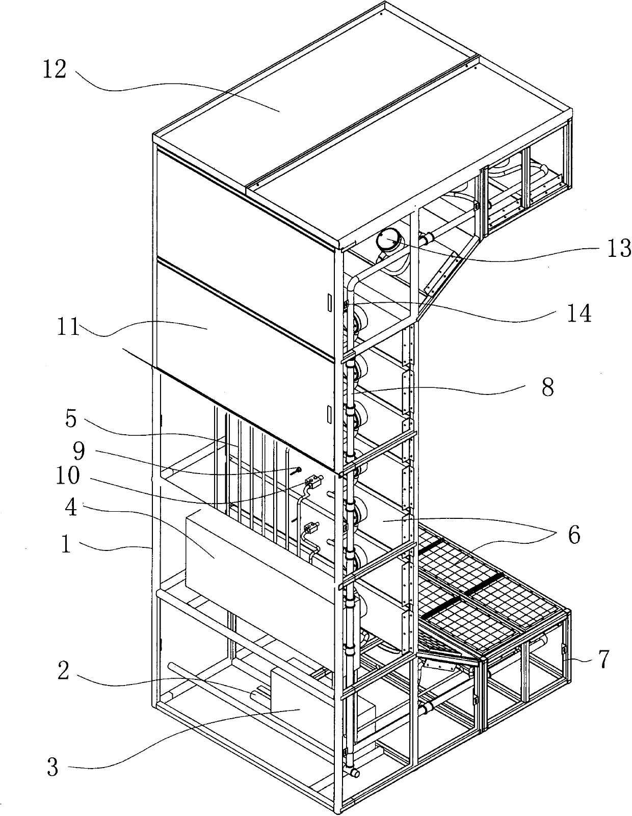
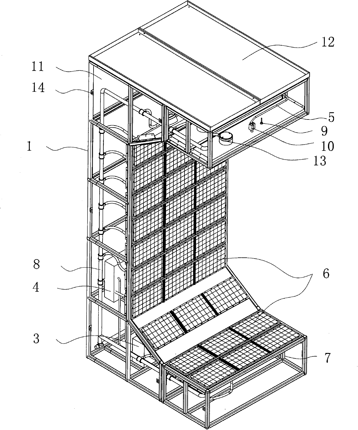
[0015] figure 1 with figure 2 A specific embodiment of the invention is shown in which figure 1 It is a structural schematic diagram of the present invention; figure 2 It is a side view structural schematic diagram of the present invention.

[0016] See figure 1 with figure 2 , a gas catalytic flameless infrared radiation heating dryer, comprising a fixed bracket assembly 1, a gas supply main pipe 2 arranged at the bottom of the fixed support assembly 1, a primary gas supply main pipe 2 connected to the The gas supply adjustment transmitter 3 and the secondary gas supply adjustment transmitter 4, the gas supply branch connected to the primary gas supply adjustment transmitter 3 and the secondary gas supply adjustment transmitter 4 5. The gas supply branch pipe 5 is vertically arranged, the fixed bracket assembly 1 is arranged in a C shape, and a gas catalytic flameless infrared radiation heater 6 is arranged inside the fixed bracket assembly 1, and the The gas catalyt...


PUM


Abstract

The invention discloses a gas-catalysis flameless infrared radiation heating dryer which comprises a fixing support assembly, a gas supply main pipe, a primary gas supply regulating transmitter, a secondary gas supply regulating transmitter and gas supply branch pipes. The fixing support assembly in C-shaped arrangement is provided with gas-catalysis flameless infrared radiation heaters and bottom connection channels, the bottom connection channels are connected with the gas-catalysis flameless infrared radiation heaters, thermocouples and safety shutoff valves are arranged on the gas-catalysis flameless infrared radiation heaters, side heat-insulation plates and top heat-insulation plates are arranged on the outer side surface of a fixing support, and explosion-proof junction box assemblies are further arranged on the gas-catalysis flameless infrared radiation heaters. The gas-catalysis flameless infrared radiation heating dryer has the advantages that the gas-catalysis flameless infrared radiation heating dryer is simple in structure, good in service performance and high in service efficiency and practicality, and can be used conveniently and quickly, the product outer surface processing efficiency can be effectively improved, heated air circulation of infrared radiation generated by the gas-catalysis flameless infrared radiation heating dryer can be prevented, accordingly, dirty spots on outer surfaces of products can be prevented, and operation time can be shortened.

Description

technical field [0001] The invention belongs to the technical field of heating and drying, in particular to a gas catalytic flameless infrared radiation heating dryer. Background technique [0002] At present, the infrared radiation heating technology commonly used at home and abroad basically uses electric heating as the heating energy. Due to the high investment cost, high management and maintenance requirements, high operating cost, short service life and high energy consumption of electric infrared radiation technology, and the use of The high-infrared quartz glass tube is easy to damage, and the circuit is prone to various safety hazards such as wire leakage and short circuit, so that users who originally used electric infrared radiation heating technology cannot use it safely and safely, and as an industrial application, it has not been able to completely pass my country's new safety standards. The specified requirements and standards for use. Simultaneously the non-cat...

Claims


Application Information

Patent Timeline
IPC IPC(8): F26B23/02
Inventor 周海波
Owner 周海波
Learn More