An automatic testing system and an automatic testing method of a continuous wave radio frequency power amplifier

An automatic test system, radio frequency power technology, applied in the direction of electronic circuit testing, etc., can solve the problems of damaged power amplifier, inaccurate test results, incomplete test process, etc.

Active Publication Date: 2014-04-23
36TH RES INST OF CETC
View PDF4 Cites 52 Cited by
  • Summary
  • Abstract
  • Description
  • Claims
  • Application Information

AI Technical Summary

Problems solved by technology

Human factors also make testing errors and improper operations unavoidable
The traditional manual testing method not only has a

Method used


Image

  • An automatic testing system and an automatic testing method of a continuous wave radio frequency power amplifier
  • An automatic testing system and an automatic testing method of a continuous wave radio frequency power amplifier
  • An automatic testing system and an automatic testing method of a continuous wave radio frequency power amplifier

Examples


Example Embodiment

[0069] First, the test system of the present invention is introduced.
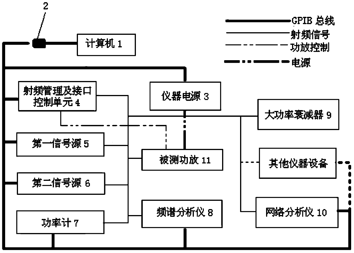
[0070] Attached figure 1 Shown is the block diagram of the power amplifier automatic test system. Including computer 1, GPIB card 2, instrument power supply 3, radio frequency management and interface control unit 4, first signal source 5, second signal source 6, power meter 7, spectrum analyzer 8, high-power attenuator 9, network analyzer 10 and other instruments and equipment.

[0071] Among them, the computer 1 provides a software platform for user interface operations, and communicates with instruments and devices through the GPIB bus, and controls and manages them. GPIB card 2 provides communication and control interfaces for computers and various instruments and equipment. The instrument power supply 3 provides voltage, current, current limiting, and undervoltage protection for the power amplifier 11 under test. The RF management and control unit 4 is an important part of the power amplifier automatic ...


PUM


Abstract

The invention relates to an automatic testing system and an automatic testing method of a continuous wave radio frequency power amplifier. The method comprises contents 1 that a computer is used for via a communication bus comprehensively managing devices such as an instrument power supply, a signal source, a power meter, a spectrum analyzer, a network analyzer, a radio frequency management and interface control unit, and a power amplifier, and automatically measuring power characteristic, saturation power, gain characteristic, output stationary waves, flatness characteristic, harmonic suppression, spurious suppression, cross modulation characteristic, group delay, and AM/PM characteristics of the radio frequency power amplifier, 2 that calibration of a radio frequency input access and a radio frequency output access is achieved; 3 that the radio frequency management and interface control unit provides all radio frequency accesses, cables are not required to be detached and radio frequency ports are not required to be replaced when indexes are tested, and TTL level, 422 level, relay driving, a serial port, and a LAN bus remote control interface are provided for different power amplifying single machines, and power amplifying transmission and reception, wave band remote control, and state monitoring are achieved; 4 and that system software modular design is achieved.

Description

technical field [0001] The invention belongs to the technical field of power amplifier testing, and in particular relates to an automatic testing system and method for indicators of continuous wave radio frequency power amplifiers. Background technique [0002] Continuous wave RF power amplifiers are an essential part of a wide variety of wireless transmitters. The main function is to amplify the continuous wave radio frequency excitation signal. There are many indicators of continuous wave RF power amplifiers, such as voltage, current, efficiency, input and output characteristics, P-1dB (1dB compression point power), Psat (saturation power), gain, output standing wave, flatness, harmonic suppression, Spurious suppression, intermodulation characteristics, phase, group delay, AM / PM (amplitude modulation / phase modulation), etc. [0003] For the test of the power amplifier, the manual test method is traditionally used. It often requires multiple engineers to operate multiple...

Claims


Application Information

Patent Timeline
IPC IPC(8): G01R31/28
Inventor 王姜铂
Owner 36TH RES INST OF CETC
Why Eureka
Try Eureka