Linear scanning device for aplanatism wave surface transformation for orthophoria synthetic aperture laser imaging radar

A synthetic aperture laser and linear scanning technology, applied in the direction of measuring devices, optics, optical components, etc., can solve the problems of large wavefront phase, unequal optical path, poor applicability, etc., to ensure precise synchronization accuracy, fast response speed, and structure simple effect

Inactive Publication Date: 2014-04-23
SHANGHAI INST OF OPTICS & FINE MECHANICS CHINESE ACAD OF SCI
View PDF5 Cites 7 Cited by
  • Summary
  • Abstract
  • Description
  • Claims
  • Application Information

AI Technical Summary

Problems solved by technology

The main problems are: the wave surface conversion scanning device of the entire emission beam is bulky, the transmission loss is large, and the vibration of the airborne platform is greatly affected; the change of the radar operating performance needs to change the phase distribution function of the light field in the emission system, and the entire system must be changed at this time. The optical and mechanical structure of the wavefront conversion scanner has poor applicability; the optical elements passed by the two polarization orthogonal separation optical paths are different, which makes the wavefront phase of the two branches easy to cause large errors
[0005] And prior art [3] (Liu L...

Method used


Image

  • Linear scanning device for aplanatism wave surface transformation for orthophoria synthetic aperture laser imaging radar
  • Linear scanning device for aplanatism wave surface transformation for orthophoria synthetic aperture laser imaging radar
  • Linear scanning device for aplanatism wave surface transformation for orthophoria synthetic aperture laser imaging radar

Examples


Embodiment Construction

[0025] The present invention will be further described below in conjunction with the accompanying drawings and embodiments, but the protection scope of the present invention should not be limited thereby.

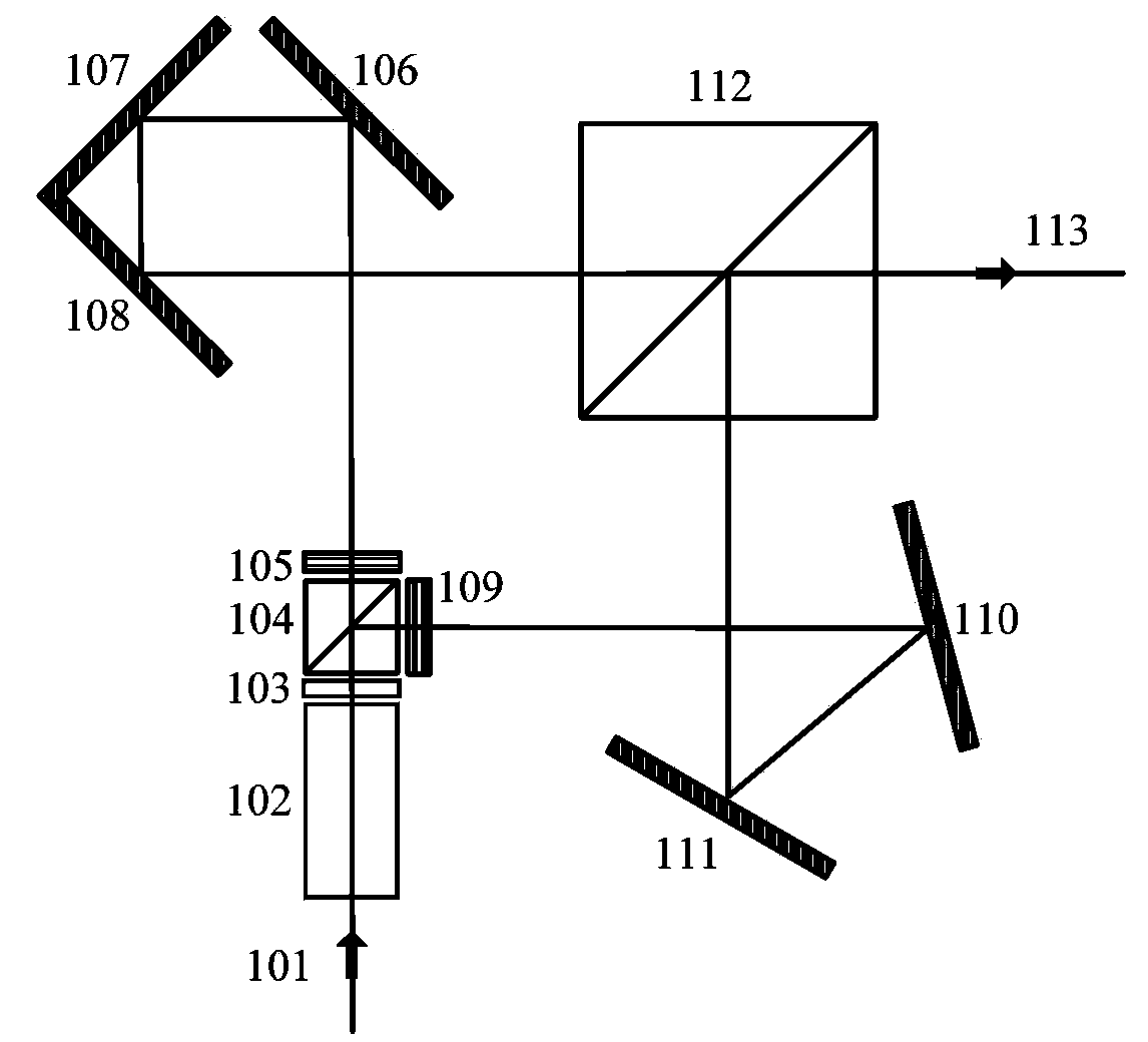
[0026] see first figure 1 , figure 1 It is an overall structural diagram of the optical path wave surface conversion linear scanning device such as direct-looking synthetic aperture laser imaging radar of the present invention. The wavefront transformation linear scanning structure and the optical path wavefront transformation structure such as along the track to the orthogonal polarization are formed.

[0027] figure 1Among them, 101 is the incident laser beam, 102 is the linear scanning structure of cross-track to direct wave front conversion, and others are optical path wave front conversion structures such as along-track to orthogonal deflection. The described along-track to orthogonal polarization equi-optical path wavefront conversion structure includes a half-wave...


PUM


Abstract

The invention discloses a linear scanning device for aplanatism wave surface transformation for an orthophoria synthetic aperture laser imaging radar. The linear scanning device for the aplanatism wave surface transformation for the orthophoria synthetic aperture laser imaging radar has the principle that a cross rail direction direct linear scanning structure adopts single reflecting mirror deflection movement linear scanning or single electro-optical crystal voltage linear driving scanning; a forward rail direction cross-polarization aplanatism wave surface transformation structure further decomposes a light beam into two space channels of a cross-polarization component; a forward rail direction cylindrical mirror is installed in each channel for wave surface transformation; a reflecting mirror is adopted for generating distance delay and wave surface inversion; two branches completely pass through the same device with completely equal optical paths; two scanning emission wave surfaces which are subjected to coaxial cross polarization are combined; finally, imaging is directly carried out on a target surface by an emission optical primary mirror. The linear scanning device for the aplantic wave surface transformation for the orthophoria synthetic aperture laser imaging radar has the advantages of simple and reliable structure and easiness in integration, two separation light paths have the completely equal optical paths and are singly driven, meanwhile, two wave surfaces carry out bidirectional scanning, single electro-optical crystal voltage driving scanning is adopted, no mechanical scanning speed is high, and the operation performance parameter of the radar can be conveniently changed by changing the reflecting mirror polarization range or the voltage modulation range.

Description

technical field [0001] The invention relates to a direct-looking synthetic aperture laser imaging radar, which is a direct-looking synthetic aperture laser imaging radar and other optical path wave surface conversion linear scanning devices. Background technique [0002] The principle of synthetic aperture laser imaging radar is taken from the principle of synthetic aperture radar in the radio frequency field, and it is the only optical imaging observation method that can obtain centimeter-level imaging resolution at long distances. Traditional synthetic aperture laser imaging radars transmit light waves and receive data under the condition of side view, and adopt optical heterodyne reception, which is greatly affected by atmospheric disturbance, vibration of moving platform, target speckle and phase change of the laser radar system itself. , it is also required that the initial phase of the beat frequency signal be strictly synchronized and a long-distance delay is required...

Claims


Application Information

Patent Timeline
IPC IPC(8): G01S7/484G01S7/491G01S17/89G02B26/10G02B27/28
CPCG01S7/4817G01S17/90G02B26/10G02B27/286
Inventor 卢智勇孙建锋职亚楠周煜蔡光宇刘立人
Owner SHANGHAI INST OF OPTICS & FINE MECHANICS CHINESE ACAD OF SCI
Why Eureka
Try Eureka