Optical image measuring apparatus and optical image measuring method

a technology of optical image and measuring apparatus, which is applied in the field of optical image measuring apparatus and optical image measuring method, can solve the problems of not being able to accurately use the apparatus in fields that require high resolution images, the current available ccd camera cannot follow the beat frequency of a heterodyne, and the measurement fundamentals are difficult to shorten the measurement time in view of measurement fundamentals, etc., to achieve high precision, easy acquisition, and high precision

Inactive Publication Date: 2006-04-13
KK TOPCON
View PDF28 Cites 54 Cited by
  • Summary
  • Abstract
  • Description
  • Claims
  • Application Information

AI Technical Summary

Benefits of technology

[0046] According to the present invention, it is possible to acquire the measurement depths related to the tomographic images of the object to be measured in the propagating direction of the signal light. Therefore, even when the object to be measured moves or propagates during measurement, a three-dimensional image or the like can be formed with high precision based on the acquired measurement depths.
[0047] In particular, according to the second aspect of the present invention, the plurality of tomographic images acquired based on a change in optical path length of the reference light are arranged in the measurement depth direction based on the measurement depths acquired related to the plurality of tomographic images. Therefore, the three-dimensional image or the like can be easily acquired with high precision.

Problems solved by technology

In addition, it is hard to shorten a measurement time in view of measurement fundamentals.
Therefore, it is supposedly hard to actually use the apparatus in fields that require a high resolution image, such as a medical field and an industrial field.
However, up to now, a problem has been recognized that a currently available CCD camera cannot follow the beat frequency of a heterodyne signal which is the order of several kHz to several MHz because of the low frequency response characteristic thereof.
However, when a movable object to be measured, such as a human eye which is a living tissue moves during the measurement of the object to be measured, it is likely to cause the displacement of the measurement position related to each of the x-y tomographic images to reduce the precision of the three-dimensional image or the like.
In particular, when the measurement interval for the x-y tomographic images in the measurement depth direction is displaced, the above-mentioned assumption related to the formation of the three-dimensional image or the like is not satisfied, so the precision of the image significantly reduces.

Method used


Image

  • Optical image measuring apparatus and optical image measuring method
  • Optical image measuring apparatus and optical image measuring method
  • Optical image measuring apparatus and optical image measuring method

Examples


first embodiment

[Structure of Apparatus]

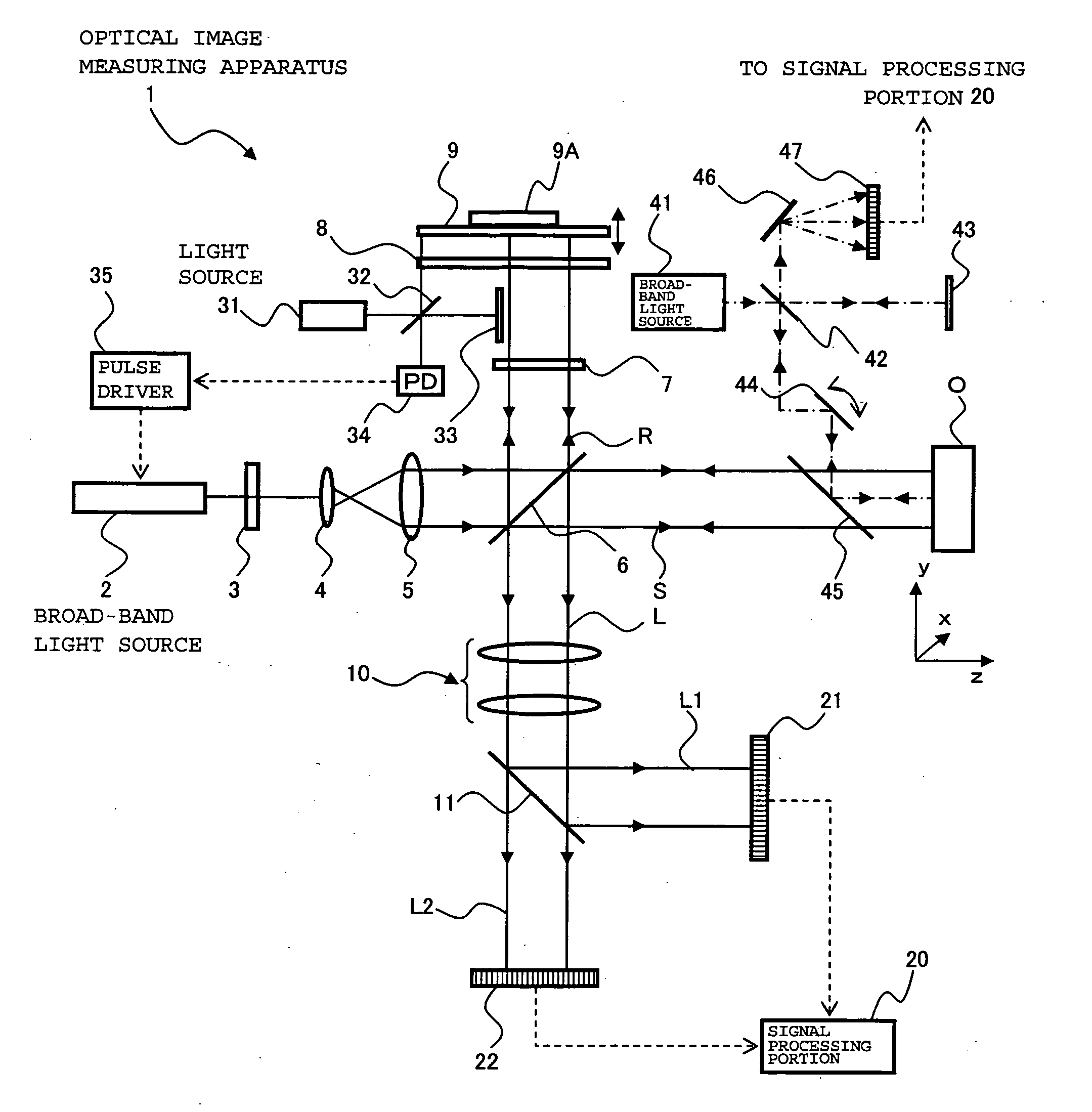
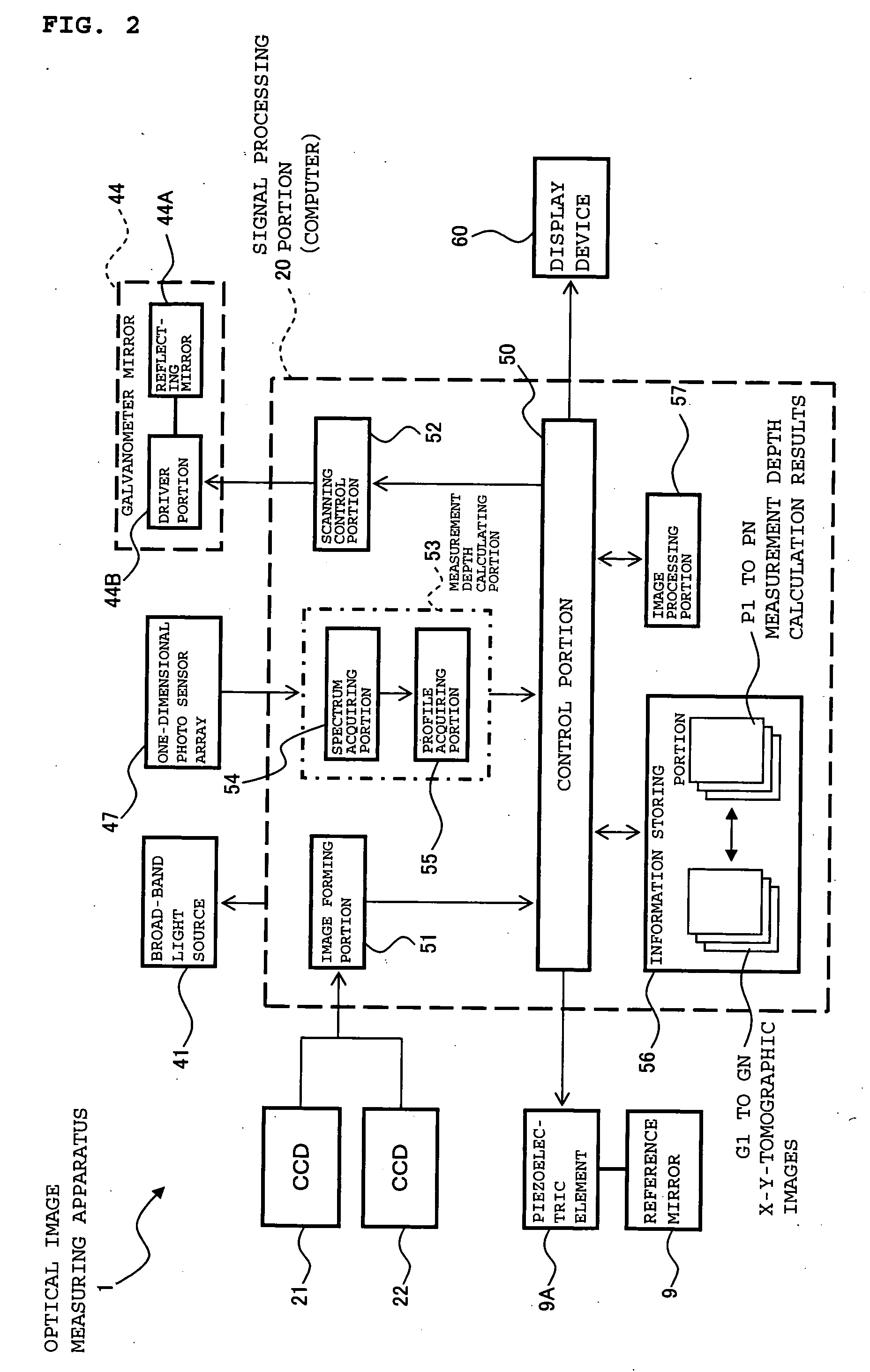
[0062] An optical image measuring apparatus according to the first embodiment of the present invention will be described with reference to FIGS. 1 and 2. FIG. 1 illustrates a schematic structure of an optical system of the optical image measuring apparatus according to this embodiment and FIG. 2 illustrates a structure of a control system thereof. The optical image measuring apparatus according to this embodiment is an apparatus used to form a tomographic image and a surface image of an object to be measured and a three-dimensional image thereof, for example, in the medical field and the industrial field. The object to be measured is an object which is made of a scattering medium such as a human eye, for example, in the medical field.

[Structure of Optical System]

[0063] First, referring to FIG. 1 the structure of the optical image measuring apparatus according to the embodiment is explained. The optical image measuring apparatus 1 includes a broad-band ligh...

modified examples

[0157] In the above-mentioned embodiment, the scanning with the auxiliary signal light is performed using the galvanometer mirror. However, the scanning means in the present invention is not limited to the galvanometer mirror and thus an arbitrary structure capable of suitably performing the scanning with the auxiliary signal light can be employed.

[0158] The wavelength filter is used as the combining and separating means in the present invention, for combining the auxiliary signal light with the signal light and separating the auxiliary signal light from the signal light. A beam splitter or the like can be alternatively used.

[0159] The one-dimensional photo sensor array is used as the auxiliary detection means in the present invention, for detecting the auxiliary interference light. For example, a two-dimensional photo sensor array such as a CCD may be used instead. In view of the precision of the formed three-dimensional image or the like, it may be desirable that a one-dimension...

second embodiment

[0165] An optical image measuring apparatus according to a second embodiment of the present invention will be described. In the first embodiment, the light source (broad-band light source 41) different from the light source for image measurement (broad-band light source 2) is provided to acquire the measurement depth related to the X-y tomographic image. In contrast to this, in this embodiment, a part of interference light caused based on the light source for image measurement is detected to acquire the measurement depth related to the X-y tomographic image.

[0166]FIG. 7 illustrates an example of the optical image measuring apparatus according to this embodiment. An optical image measuring apparatus 100 shown in FIG. 7 has substantially the same structure as that of the optical image measuring apparatus 1 according to the first embodiment. In FIG. 7, same reference symbols are provided to the same constituent portions as those in FIG. 1.

[0167] The optical image measuring apparatus ...


PUM


Abstract

Provided is an optical image measuring apparatus forming a three-dimensional image based on tomographic images of an object, acquired at various depths even when the object moves during measurement. Including a half mirror (6) for dividing a light beam signal light (S) and reference light (R), a frequency shifter (8), a reference mirror (9) and a piezoelectric element (9A) used to change an optical path length of the reference light (R), CCDs (21, 22) for receiving interference light beams (L) resulting from interference light produced by superimposing the signal light (S) and the reference light (R) on each other by the half mirror (6) and outputting detection signals, an image forming portion for forming tomographic images based on the detection signals, a measurement depth calculating means (53), and an image processing portion (57). Forming a three-dimensional image or the like based on the arranged tomographic images.

Description

BACKGROUND OF THE INVENTION [0001] 1. Field of the Invention [0002] The present invention relates to an optical image measuring apparatus that applies a light beam to an object to be measured, particularly a light scattering medium, and produces a surface form or inner form of the object to be measured by detecting a reflected light beam or a transmitted light beam. In particular, the present invention relates to an optical image measuring apparatus for measuring the surface form or inner form of the object to be measured by using an optical heterodyne detection method to produce the image of the measured form. [0003] 2. Description of the Related Art [0004] In recent years, attention has been given to optical imaging technique that produces an image of a surface or inner portion of an object to be measured using a laser light source or the like. This optical imaging technique is not hazardous to human bodies in contrast to the conventional X-ray CT. Therefore, the development of ap...

Claims


Application Information

Patent Timeline
Patent Type & Authority Applications(United States)
IPC IPC(8): G01B11/02
CPCG01B11/2441G01B9/02007G01B9/02003G01B9/02044G01B9/02027G01B9/02091G01B9/02014G01B9/02069G01B2290/70G01B2290/65G01B2290/45
Inventor CHAN, KINPUIAKIBA, MASAHIROFUKUMA, YASUFUMIOTSUKA, HIROYUKITSUKADA, HISASHIYUMIKAKE, KAZUHIKO
Owner KK TOPCON
Why Eureka
Try Eureka