Stainless steel substrate solar battery in adjustable-band-gap quantum well structure and preparation method thereof

A technology of solar cells and stainless steel, applied in sustainable manufacturing/processing, circuits, photovoltaic power generation, etc., can solve the problems of poor market competitiveness of thin-film solar cells, poor stability of photo-induced performance of solar cells, and low photoelectric conversion efficiency, etc. Corrosion-resistant tunneling barrier, light weight, and improved photoelectric conversion efficiency

Active Publication Date: 2014-04-23
SHENYANG INST OF ENG
View PDF4 Cites 10 Cited by
  • Summary
  • Abstract
  • Description
  • Claims
  • Application Information

AI Technical Summary

Problems solved by technology

However, since the bandgap width of amorphous or microcrystalline silicon (Si) film is about 1.7eV, it is very insensitive to the long wavelength of solar radiation spectrum, making its photoelectric conversion efficiency low, and there is also an obvious photodegradation effect, making solar energy The stability of the photoinduced performance of the battery is poor, resulting in poor market competitiveness of thin-film solar cells

Method used


Image

  • Stainless steel substrate solar battery in adjustable-band-gap quantum well structure and preparation method thereof
  • Stainless steel substrate solar battery in adjustable-band-gap quantum well structure and preparation method thereof
  • Stainless steel substrate solar battery in adjustable-band-gap quantum well structure and preparation method thereof

Examples


Embodiment 1

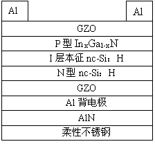
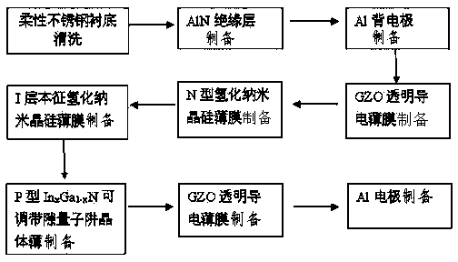
[0036] The structural diagram of the stainless steel substrate solar cell of the adjustable bandgap quantum well structure of the present embodiment is as follows figure 1 Shown, the preparation method is:

[0037] (1) After ultrasonically cleaning the stainless steel flexible substrate with deionized water for 5 minutes, use N 2 Blow dry and send into the magnetron sputtering reaction chamber, at 9.0×10 -4 Under the condition of Pa vacuum, the AlN insulating layer is deposited and prepared, and the Ar and N 2 Mixed gas reaction source, Ar and N 2 The flow rate ratio is 10:1, the substrate substrate is heated to 100°C, and the deposition time is 30min. At this time, the structure is AlN insulating layer / flexible stainless steel substrate;

[0038] (2) Continue to prepare the metal Al back electrode by magnetron sputtering, use Ar as the gas reaction source, the Ar flow rate is 10sccm, the substrate temperature is 50°C, and the deposition time is 3min. The structure...

Embodiment 2

[0049] The structural diagram of the stainless steel substrate solar cell of the adjustable bandgap quantum well structure of the present embodiment is as follows figure 1 Shown, the preparation method is:

[0050] (1) After ultrasonically cleaning the stainless steel flexible substrate with deionized water for 5 minutes, use N 2 Blow dry and send into the magnetron sputtering reaction chamber, at 9.0×10 -4 Under the condition of Pa vacuum, the AlN insulating layer is deposited and prepared, and the Ar and N 2 Mixed gas reaction source, Ar and N 2 The flow rate ratio is 10:1, the substrate substrate is heated to 150°C, and the deposition time is 45min. At this time, the structure is AlN insulating layer / flexible stainless steel substrate;

[0051] (2) Continue to prepare the metal Al back electrode by magnetron sputtering, use Ar as the gas reaction source, the Ar flow rate is 12sccm, the substrate temperature is 150°C, and the deposition time is 5min. The structure at...

Embodiment 3

[0059] The structural diagram of the stainless steel substrate solar cell of the adjustable bandgap quantum well structure of the present embodiment is as follows figure 1 Shown, the preparation method is:

[0060] (1) After ultrasonically cleaning the stainless steel flexible substrate with deionized water for 5 minutes, use N 2 Blow dry and send into the magnetron sputtering reaction chamber, at 9.0×10 -4 Under the condition of Pa vacuum, the AlN insulating layer is deposited and prepared, and the Ar and N 2 Mixed gas reaction source, Ar and N 2 The flow rate ratio is 10:1, the substrate substrate is heated to 300°C, and the deposition time is 60min. At this time, the structure is AlN insulating layer / flexible stainless steel substrate;

[0061] (2) Continue to prepare the metal Al back electrode by magnetron sputtering, use Ar as the gas reaction source, the Ar flow rate is 20sccm, the substrate temperature is 350°C, and the deposition time is 10min. The structure a...


PUM

PropertyMeasurementUnit
purityaaaaaaaaaa

Abstract

The invention belongs to the technical field of flexible solar battery manufacturing, and particularly relates to a stainless steel substrate solar battery in an adjustable-band-gap quantum well structure and a preparation method thereof. The stainless steel substrate solar battery provided by the invention is of the following concrete structure: Al electrode / GZO (gallium zinc oxide) / P type In<x>Ga<1-x>N / I layer intrinsic nc-Si:H / N type nc-Si:H / GZO / Al back electrode / AlN insulation layer / flexible stainless steel substrate. The preparation method of the stainless steel substrate solar battery comprises the steps that firstly, magnetron sputtering is carried out for preparing an AlN insulation layer and an Al back electrode, then, ECR-PEMOCVD is adopted for sequentially depositing a GZO based transparent conducting film, an N type nc-Si:H film, an I layer intrinsic nc-Si:H film, a P type In<x>Ga<1-x>N film and a GZO film, and finally, the metal Al electrode is prepared. The stainless steel substrate solar battery in the adjustable-band-gap quantum well structure has the advantages that the flexibleness is excellent, the weight is light, the carrying is convenient, the industrialization potential and the market space are realized, in addition, the preparation process is simple, and the scale production can be realized.

Description

technical field [0001] The invention belongs to the technical field of flexible solar cell manufacturing, in particular to a stainless steel substrate solar cell with an adjustable bandgap quantum well structure and a preparation method. Background technique [0002] The first-generation solar cells of silicon crystals are currently in a dominant position in industrial production and the market due to their high conversion efficiency. However, due to the need to consume a large amount of raw materials and high cost, it has become a major obstacle to the development of solar cells. In order to save raw materials and further promote the development of solar cells, thin-film solar cells have become a research hotspot of solar cells in recent years. [0003] Traditional thin-film solar cell structures use rigid materials and tempered glass materials as substrates, which limits their application range. As the cost of solar cells becomes lower and lower, more and more such b...

Claims


Application Information

Patent Timeline
Patent Type & Authority Applications(China)
IPC IPC(8): H01L31/0352H01L31/0392H01L31/075H01L31/18H01L31/0224
CPCY02E10/50H01L31/022483H01L31/03529H01L31/03926H01L31/075H01L31/20H01L21/0254H01L21/02554H01L21/02565H01L21/0262H01L31/03048H01L31/035209H01L31/035236H01L31/03762H01L31/1848H01L31/202Y02E10/544Y02E10/548Y02P70/50
Inventor 张铁岩张东鞠振河赵琰李昱材宋世巍王健王刚边继明刘宝丹
Owner SHENYANG INST OF ENG
Why Eureka
Try Eureka