Particulate matter electricity carrying capacity measurement device and method

A technology for measuring devices and particles, which is applied in the direction of measuring devices, measuring electrical variables, particle charging/ionization places, etc., can solve the problems that the removal efficiency is less than 50%, and the removal effect of sub-micron particles is not ideal, and achieves Simple structure, reasonable design, and the effect of controlling emissions

Active Publication Date: 2014-04-30
ZHEJIANG UNIV
View PDF6 Cites 16 Cited by
  • Summary
  • Abstract
  • Description
  • Claims
  • Application Information

AI Technical Summary

Problems solved by technology

[0003] In the prior art, the use of electrostatic precipitators to control atmospheric particulate matter is a relatively common method. The dust removal efficiency of electrost

Method used


Image

  • Particulate matter electricity carrying capacity measurement device and method
  • Particulate matter electricity carrying capacity measurement device and method
  • Particulate matter electricity carrying capacity measurement device and method

Examples


Example Embodiment

[0034] Example 1

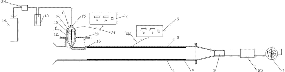
[0035] refer to Figure 1~4 , a device for measuring the charged amount of particulate matter, comprising a gas cylinder 14 connected in sequence, a particle generating device 13, a charger, a detector and an induced draft fan 4, and a first flow rate is provided between the gas cylinder 14 and the particle generating device 13 Meter 24, a second flow meter 25 is arranged between the detector and the induced draft fan 4; the charger is arranged at the left end of the detector, and the right end of the detector is communicated with the induced draft fan through a pipeline; the charger is connected to the charger through the first wire 21 The electrical high-voltage power supply 7 is connected, and the detector is connected with the detector high-voltage power supply 6 through the second wire 22 .

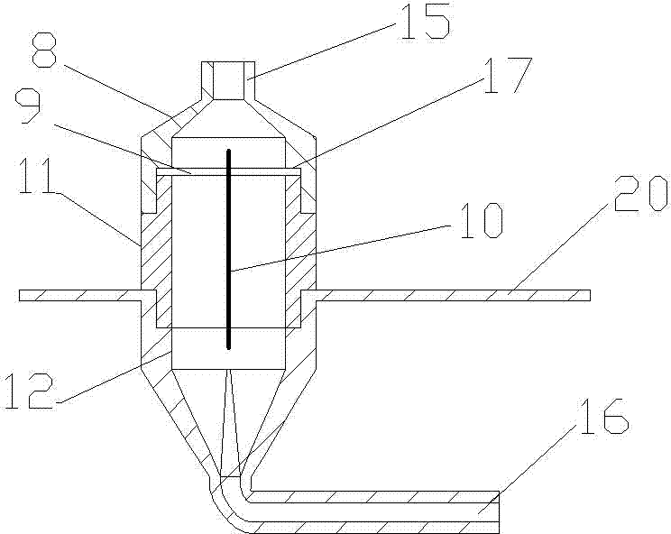
[0036] The charger includes the upper end 8 of the charger, the middle part of the charger formed by the ground electrode 11 of the charger, the lower end 12 of t...

Example Embodiment

[0048] Example 2

[0049] refer to Figure 1~4 , a method for measuring the charge of particulate matter, comprising the steps of:

[0050] (1) After the airflow output by the gas cylinder 14 passes through the first flow meter 24 to control the flow rate, it is mixed with particulate matter in the particle generating device 13 and enters the charge through the airflow inlet 15;

[0051] (2) After the particulate matter entering the charger is charged by the corona discharge between the discharge electrode 10 and the ground electrode 11 of the charger, it moves horizontally from the air outlet 16 into the detector; where the area of ​​the air outlet and the main structure of the charger The area of ​​the hollow cavity circle is equal;

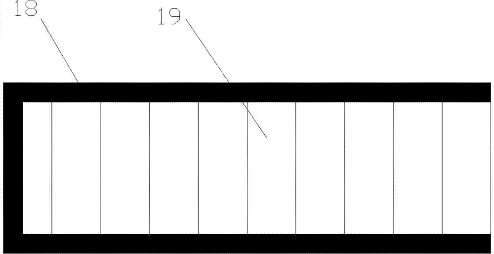
[0052] (3) After the particles enter the detector, they move directionally under the action of the uniform electric field generated between the upper plate 5 of the detector and the lower plate 2 of the detector, and land on different positio...


PUM


Abstract

The invention relates to a particulate matter electricity carrying capacity measurement device and method. The device comprises a gas bottle, a particle generating device, an electricity carrying device, a detector and a draught fan which are sequentially connected, wherein a first flow meter is arranged between the gas bottle and the particle generating device; a second flow meter is arranged between the detector and the draught fan; the electricity carrying device is arranged at the left end of the detector; the right end of the detector is communicated with the draught fan by a pipeline; the electricity carrying device is connected with a high-voltage power supply of the electricity carrying device by a first lead; the detector is connected with a high-voltage power supply of the detector by a second lead. The particulate matter electricity carrying capacity measurement device provided by the invention is simple in structure, is reasonable in design, and can accurately measure the electricity carrying capacity of each particle in an electrostatic precipitator, thereby studying the electricity carrying mechanism of particles of the electrostatic precipitator, and facilitating to the design and research of the electrostatic precipitation system, so that the precipitation efficiency of the electrostatic precipitator is improved, and the emission of coal burning flue gas particulate matters can be controlled effectively.

Description

technical field [0001] The invention relates to a device and method for measuring charge quantity, in particular to a device and method for measuring charge quantity of particulate matter, belonging to the field of environmental protection. Background technique [0002] With the development of industry, my country's current air pollution problem is becoming more and more serious, and the number of pollutants is increasing day by day. Among them, the content of solid particles accounts for the first place in my country's air pollutants, and its concentration is an important indicator to measure the degree of air pollution. The main source of atmospheric particulate matter in my country is a large amount of smoke and dust emitted by coal-fired power plants, and these smoke and dust basically belong to inhalable particulate matter PM10 and PM2.5, which are extremely harmful to human health. This issue has attracted widespread attention from all walks of life across the country. ...

Claims


Application Information

Patent Timeline
IPC IPC(8): B03C3/38G01R29/24
Inventor 高翔郑成航骆仲泱岑可法倪明江张涌新施正伦王毅周劲松方梦祥程乐鸣王勤辉王树荣余春江
Owner ZHEJIANG UNIV
Why Eureka
Try Eureka