Integrated desoldering system conducting upper hot air heating and lower hot air heating synchronously
What is Al technical title?
Al technical title is built by PatSnap Al team. It summarizes the technical point description of the patent document.
A hot air and heating head technology, applied in electric heating devices, metal processing, welding equipment, etc., can solve problems such as not being able to adapt to high-end circuit board assembly production and repair, affecting work quality and production efficiency, and poor local welding of BGA. The effect of desoldering and mounting precision, improving the success rate of welding, and no safety hazard
Active Publication Date: 2014-04-30
SHENZHEN ZHUO MAO TECH
View PDF4 Cites 6 Cited by
Summary
Abstract
Description
Claims
Application Information
AI Technical Summary
This helps you quickly interpret patents by identifying the three key elements:
Problems solved by technology
Method used
Benefits of technology
Problems solved by technology
In the automatic assembly production and rework of circuit boards, because the upper and lower heaters cannot be completely aligned, there will be inconsistencies in the temperature of the front and back of the PCB board, resulting in many problems such as poor local welding of BGA, stable performance and accuracy: a. Traditionally, heaters It is an independent movement, and its effect is not great. Actually, in the automatic assembly production and repair of circuit boards, the upper heater and the lower heater must be heated at the center of the component at the same time to ensure the success rate of desoldering; this traditional structure Affects work quality and production efficiency; b. Traditionally, the heater is fixed, which cannot adapt to the automatic assembly and repair of high-end circuit boards. It is limited in actual operation, and the PCB board is heated and deformed, resulting in poor desoldering accuracy and cannot be guaranteed Low success rate and work efficiency
Method used
Image
Click on the blue label to locate the original text in one second.
Reading with bidirectional positioning of images and text.
Examples
Embodiment Construction
[0030] The technical solutions of the present utility model will be further specifically described below through the embodiments and in conjunction with the accompanying drawings.
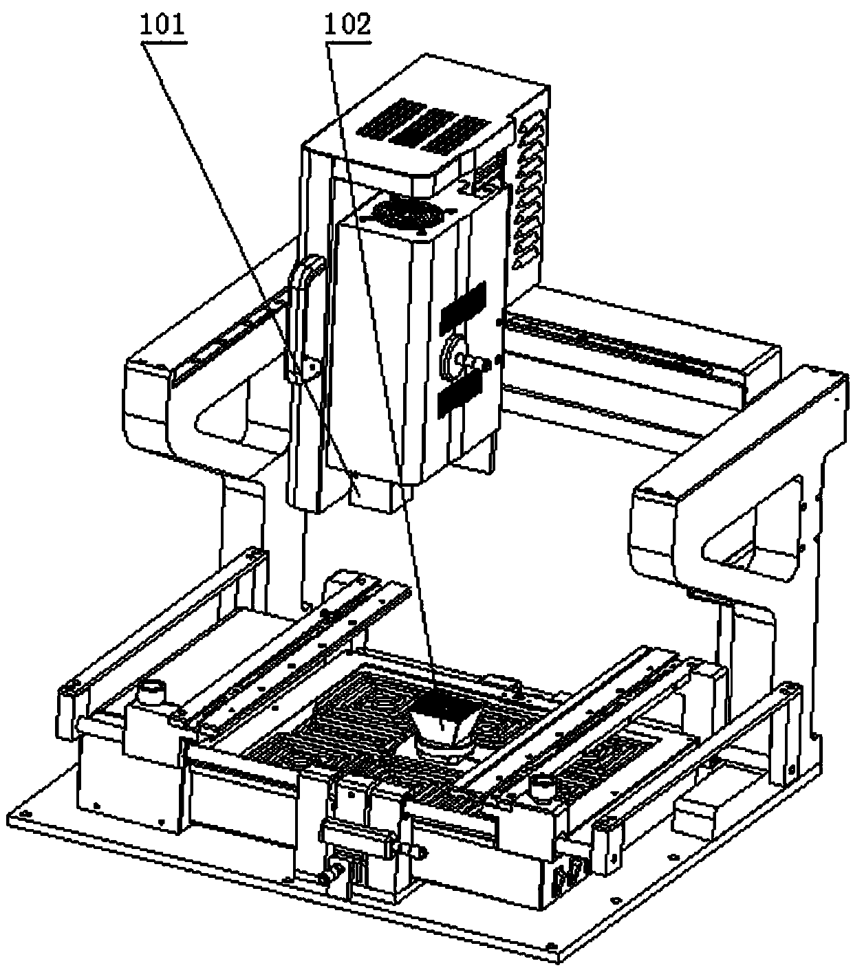
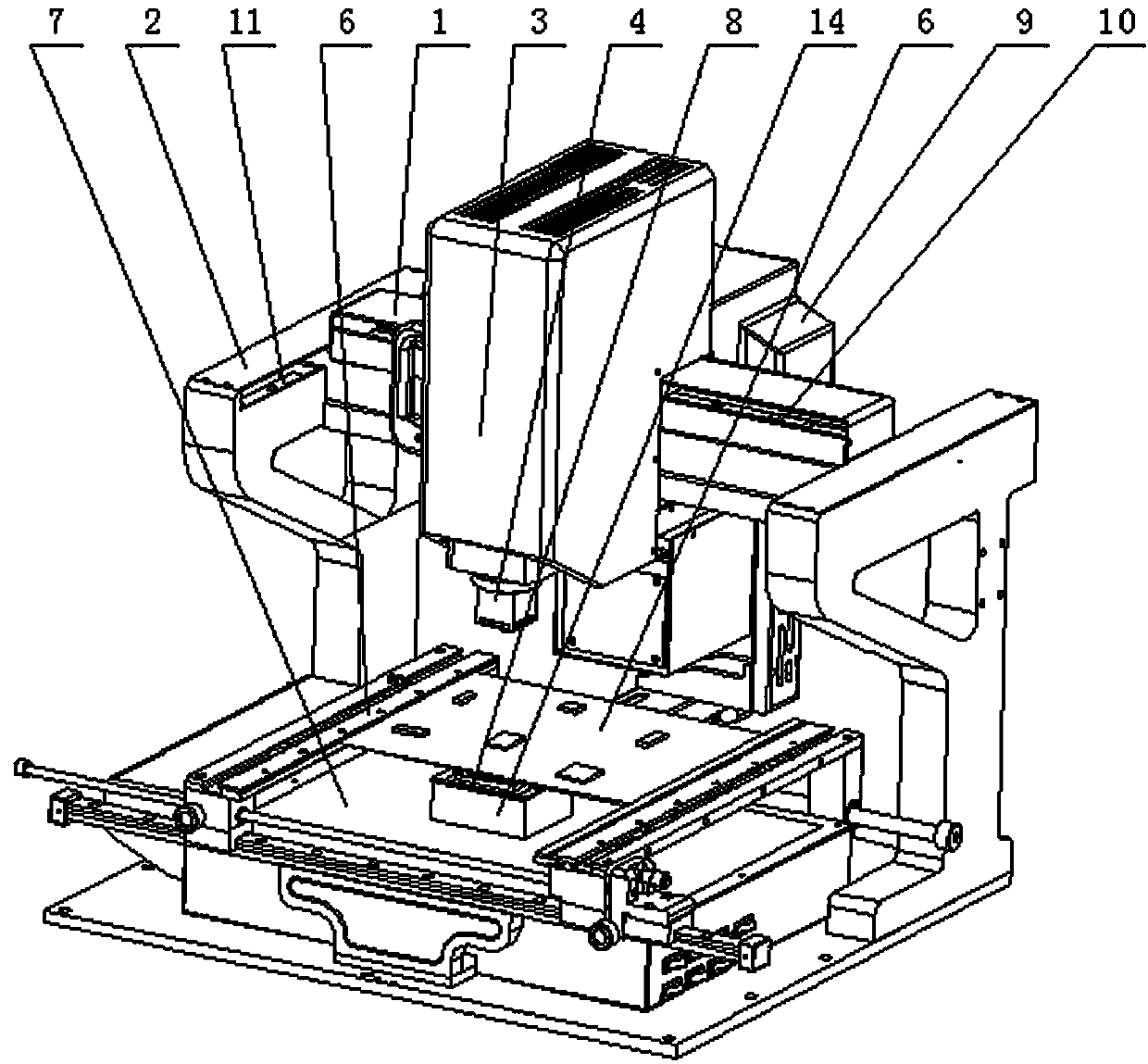
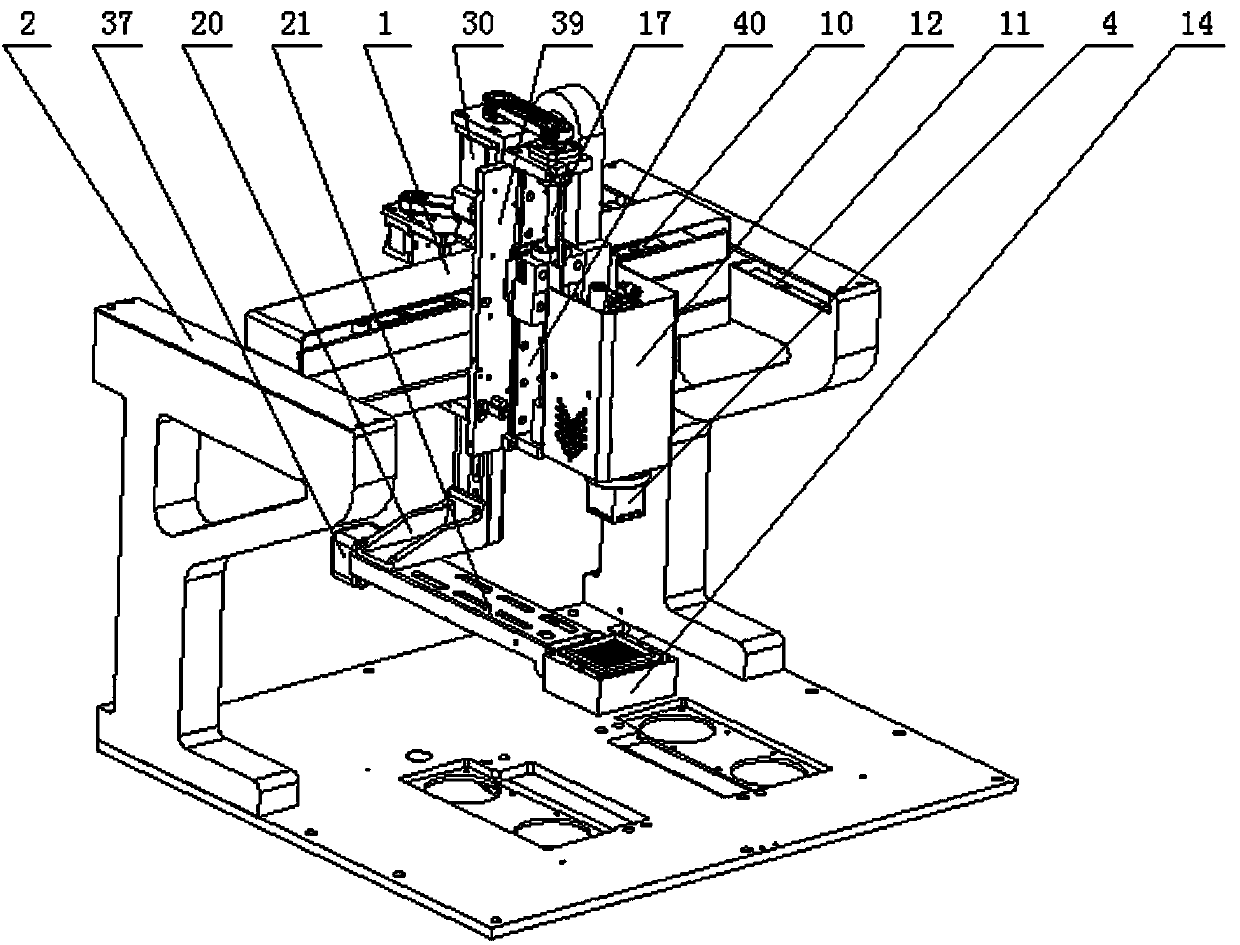
[0031] figure 2 It is a schematic diagram of the implementation structure of the present invention; image 3 It is a schematic diagram of the overall structure of the present invention; Figure 4a , 4b It is a schematic diagram of structural decomposition of the present invention; Figure 5 yes Figure 4a The front view of the structure shown; Figure 6 yes Figure 4a Right view of the structure shown; Figure 7 is a picture Figure 6 Section A-A is shown. Depend on figure 2 to combine image 3 ,Figure 4, Figure 5 , Figure 6 , Figure 7 It can be seen that the integrated desoldering system with synchronous heating of upper and lower hot air is mainly composed of an upper heating device, a lower heating device and a synchronization mechanism, wherein the upper heating device consist...
PUM
Abstract
Provided is an integrated desoldering system conducting upper hot air heating and lower hot air heating synchronously. The integrated desoldering system comprises an upper heating device, a lower heating device and a synchronization mechanism. The upper heating device is composed of an upper heating group, an X-axis cross beam, a Y-axis cross beam, an upper heating cover, an upper heating tuyere, an X-direction guide rail, a Y-direction guide rail, a Z-direction guide rail, a ball screw and an upper synchronous wheel. The lower heating device is composed of a lower heating group and a heater through-connection body. The synchronization mechanism is composed of a manipulator front fixing plate, a manipulator upper arm, an arm connecting part, a manipulator front arm, an upper inductor, a lifting induction sheet, a lower inductor, a manipulator rear fixing plate, manipulator side fixing plates, a manipulator upper fixing plate, a ball screw, a lead screw nut, an arm braking component and a manipulator lower fixing plate. According to the integrated desoldering system conducting upper hot air heating and lower hot air heating synchronously, the upper heating group and the lower heating group move synchronously and move freely in the X direction, the Y direction and the Z direction; the desoldering and surface mount precision is effectively guaranteed; the automation is high, and the working efficiency is improved.
Description
technical field [0001] The invention relates to the technical field of PCB board desoldering, in particular to an integrated desoldering system with synchronous heating of upper and lower hot air. Background technique [0002] In the field of automatic assembly production and repair of circuit boards, there are more and more high-end precision electronic products. When precision mounting, heating and cooling of components, the accuracy, uniformity and stability of temperature control are very important. The accuracy and stability of the temperature are mainly reflected in the heating and cooling time, the heating and cooling rate and the temperature uniformity of the heated area. In addition to highly automated applications, it is also necessary to have mechanisms such as miniaturization, modularization, precise mounting, and high-precision temperature control to ensure the operating accuracy of the equipment. [0003] Traditional upper and lower heaters (such as figure 1 ...
Claims
Application Information
Patent Timeline
Application Date:The date an application was filed.
Publication Date:The date a patent or application was officially published.
First Publication Date:The earliest publication date of a patent with the same application number.
Issue Date:Publication date of the patent grant document.
PCT Entry Date:The Entry date of PCT National Phase.
Estimated Expiry Date:The statutory expiry date of a patent right according to the Patent Law, and it is the longest term of protection that the patent right can achieve without the termination of the patent right due to other reasons(Term extension factor has been taken into account ).
Invalid Date:Actual expiry date is based on effective date or publication date of legal transaction data of invalid patent.