Welding process and application device of corrugated pipe assembly

A corrugated pipe component and welding process technology, applied in the field of corrugated tube component welding process and its application device, can solve the problems of easy virtual welding, low welding strength, high welding precision requirements, etc., and achieve favorable adjustment, good heat dissipation, high efficiency effect

Active Publication Date: 2014-04-30
DONGGUAN HUAHUI PRECISION MASCH CO LTD
View PDF5 Cites 1 Cited by
  • Summary
  • Abstract
  • Description
  • Claims
  • Application Information

AI Technical Summary

Problems solved by technology

Welded metal bellows has a variety of structural forms and welding methods. The welding methods are mainly divided into inner circle welding and outer circle welding; in actual use, there are the following problems: a. The weakest link of the bellows is the welding between the two ends and the substrate, which is easy to fail Welding and weld strength are not enough; b. After welding, the bellows need heat treatment and stable length. Usually, the two ends are fixed, and the bellows assembly is also called "soft" by stretching and pressing. Extrusion and collision of the metal parts at the ends will easily cause unrecoverable deformation or damage to the waveforms of the wave plates at both ends, affect the strength of the inner round solder ball, and is not conducive to the elastic linear relationship of the bellows; c. The welding accuracy of the bellows is high, so In actual production, in order to ensure the accuracy, the welding efficiency is often low, especially when welding the outer circle, the method used is single-wave welding, that is, after one wave of welding, the tooling is disassembled, and then a wave of welding is returned. The concentricity of the wave core in this welding met

Method used


Image

  • Welding process and application device of corrugated pipe assembly
  • Welding process and application device of corrugated pipe assembly
  • Welding process and application device of corrugated pipe assembly

Examples


Embodiment Construction

[0031] The present invention will be further described below in conjunction with accompanying drawing:

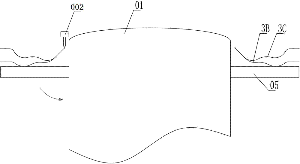
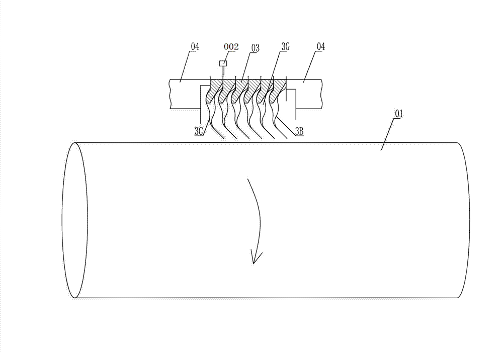
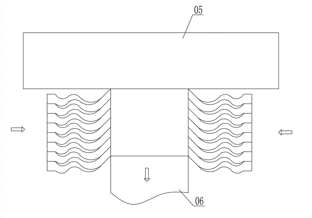
[0032] Such as Figure 1 to Figure 8As shown, the technical scheme adopted by the present invention is as follows, a welding process of a bellows assembly, the steps of which include: a. Welding to form a mother and daughter piece 3G: the wave plate convex plate 3B and the wave plate concave plate 3C are formed according to the wave plate concave plate 3C is inserted into the rotating shaft 01 in the order that the lower wave plate convex piece 3B is on the top, and the rotating shaft 01 is rotated so that the welding mechanism 002 welds the inner ring of the wave plate convex piece 3B and the wave plate concave piece 3C to form a master piece 3G; b. Welding Form the corrugated tube core 3A: insert the spacer ring 02 between the wave plate convex plate 3B and the wave plate concave plate 3C of the mother-child plate 3G, and insert at least two mother-child plates 3G inserte...


PUM


Abstract

The invention discloses a welding process and an application device of a corrugated pipe assembly. The welding process includes steps that a, primary and secondary pieces are formed by welding; b, a corrugated pipe core is formed by welding; c, a corrugated pipe is formed by welding; d, the corrugated pipe assembly is formed by welding; a sealing performance test is performed. A corrugated pipe sealing device is characterized by comprising the corrugated pipe assembly, a casing, a stationary ring and a moving ring, wherein the left end of the casing is embedded into a groove face, the stationary ring is arranged in a step surface, the moving ring is attached to the end face of the stationary ring, and a contact face forms a sealing end face. The welding process and the application device of the corrugated pipe assembly have the advantages that the welding efficiency is high, the accuracy is good, the elastic compensation is stable, and the service life is long.

Description

technical field [0001] The invention relates to a mechanical sealing device, in particular to a welding process of a bellows assembly and an application device thereof. Background technique [0002] Welded metal bellows mechanical seals are widely used in various centrifugal pumps, and are popular for their characteristics of uniform elastic force, natural balance, convenient installation, and wide temperature range. Welded metal bellows has a variety of structural forms and welding methods. The welding methods are mainly divided into inner circle welding and outer circle welding; in actual use, there are the following problems: a. The weakest link of the bellows is the welding between the two ends and the substrate, which is easy to fail Welding and weld strength are not enough; b. After welding, the bellows need heat treatment and stable length. Usually, the two ends are fixed, and the bellows assembly is also called "soft" by stretching and pressing. Extrusion and collis...

Claims


Application Information

Patent Timeline
IPC IPC(8): B23K31/02F04D29/10
CPCB23K31/027B23K31/125B23K2101/06F04D29/10
Inventor 郭文德
Owner DONGGUAN HUAHUI PRECISION MASCH CO LTD
Why Eureka
Try Eureka