Signal processing method based on laser radar waveform of coherent system

A technology of laser radar and signal processing, which is applied in the direction of electromagnetic wave re-radiation, radio wave measurement system, utilization of re-radiation, etc., can solve the problems of echo signal pulse compression performance degradation, etc., to ensure pulse compression performance, reduce peak power, The effect of system simplification

Active Publication Date: 2014-04-30
INST OF ELECTRONICS CHINESE ACAD OF SCI
View PDF2 Cites 11 Cited by
  • Summary
  • Abstract
  • Description
  • Claims
  • Application Information

AI Technical Summary

Problems solved by technology

[0013] The technical problems to be solved mainly include the following points: 1. Solve the problem of broadband signal generation and the high peak power of the transmitted signal required by the coherent laser radar for high resolution; 2. Solve the problem of high-speed sampling

Method used


Image

  • Signal processing method based on laser radar waveform of coherent system
  • Signal processing method based on laser radar waveform of coherent system
  • Signal processing method based on laser radar waveform of coherent system

Examples


Embodiment 1

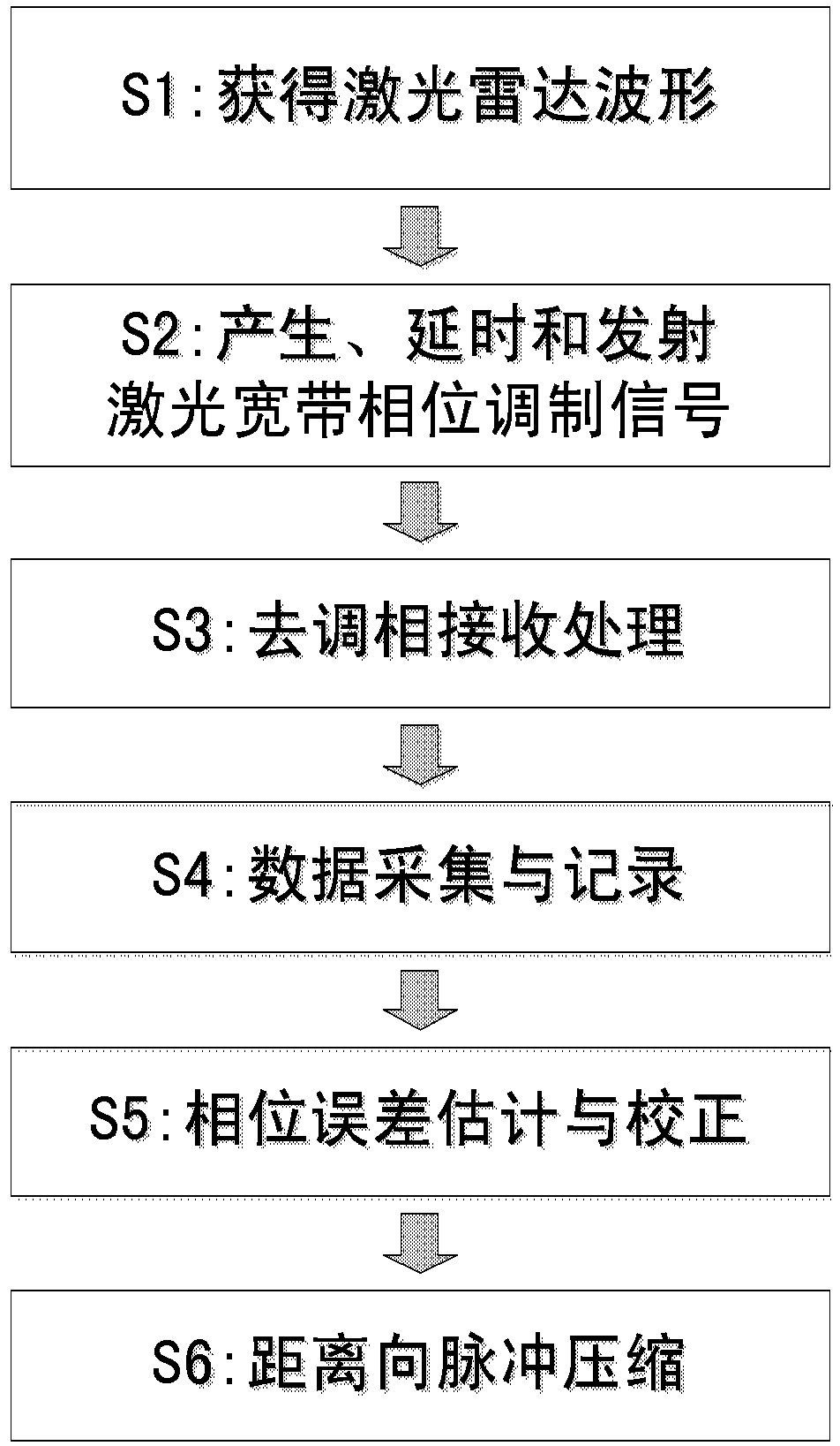
[0052] Example 1: Figure 4 It shows the specific implementation schematic diagram of the coherent laser radar dephasing reception of the present invention, which mainly includes: a laser light source, a crystal oscillator, a timer, a modulation signal generator, a laser phase modulator, an optical fiber delay line, an optical fiber amplifier at the transmitting end, Optical fiber amplifier at the receiving end, laser coherent detection demodulator, A / D converter, data recorder and pulse compression processing unit, in which:

[0053] The timer receives the crystal oscillator signal and outputs the analog-to-digital clock signal, timing pulse signal and strobe pulse signal;

[0054] The modulation signal generator receives the timing pulse signal, generates and outputs the modulation signal;

[0055] The laser phase modulator receives the modulation signal and the laser light source signal, generates and outputs the laser phase modulation signal;

[0056] The fiber delay lin...

Embodiment 2

[0065] Example 2: Image 6 It shows the specific implementation schematic diagram of the dephasing reception of the phase error correction of the coherent laser radar of the present invention, which mainly includes: laser light source signal, modulation signal, laser phase modulator, optical fiber delay line, optical fiber amplifier at the transmitting end, coupler , optical fiber amplifier at the receiving end, laser coherent detection demodulator, A / D converter and data recorder, phase error correction unit and pulse compression processing unit, wherein:

[0066] The laser phase modulator receives the modulation signal and the laser light source signal, generates and outputs the laser phase modulation signal;

[0067] The fiber delay line delays the laser phase modulation signal and outputs the delayed laser phase modulation signal;

[0068] The optical fiber amplifier at the transmitting end receives the laser phase modulation signal and transmits the amplified laser phase...


PUM

PropertyMeasurementUnit
Pulse widthaaaaaaaaaa
Sampling rateaaaaaaaaaa

Abstract

The invention discloses a signal processing method based on a laser radar waveform of a coherent system. The method comprises the steps of conducting quantization on phases of chirp signals of the laser radar of the coherent system to obtain the laser radar waveform, generating laser phase modulating signals according to the laser radar waveform, on one hand, obtaining delayed laser phase modulation signals, on the other hand, amplifying and transmitting the laser phase modulating signals, conducting phase demodulating processing on received target echo signals and the delayed laser phase modulation signals, generating quadrature demodulation echo signals, utilizing an analog-digital converter for collecting and recording the quadrature demodulation echo signals, conducting phase error estimation and correction on the the quadrature demodulation echo signals to obtain the echo signals after phase error correction, conducting distance direction Fourier transform on the echo signals after the phase error correction, and obtaining a distance direction pulse compression signal of the target. The method is used for achieving laser radar high distance resolution imaging of the coherent system under the condition of greatly reducing the sampling rate of the analog-digital converter.

Description

technical field [0001] The invention belongs to the technical field of coherent system laser radar, in particular to a coherent system laser radar waveform design and its signal processing method. Laser radar, coherent system Doppler wind radar. Background technique [0002] With the improvement of the coherence of the laser light source signal, the lidar technology of the coherent system has been developed rapidly. The types and main application directions of its lidar include: [0003] Because of its coherent system, synthetic aperture lidar represents the development direction of lidar, and has important research value both for technology promotion and practical application; [0004] Research on high-resolution imaging technology (active laser imaging with a small imaging angle, which can be fused with visible light images in principle); [0005] Basic surveying and mapping (high-altitude three-dimensional lidar uses pulse compression in the range direction, and uses a...

Claims


Application Information

Patent Timeline
IPC IPC(8): G01S7/483G01S17/89
CPCG01S7/491G01S17/90
Inventor 李道京杜剑波马萌
Owner INST OF ELECTRONICS CHINESE ACAD OF SCI
Why Eureka
Try Eureka