Slag discharge system, gasifier and gasification power generation device

A slag and gasifier technology, applied in the field of gasification power generation devices, can solve the problems of installation of auxiliary equipment such as syngas cooler 71, increase in construction cost, and increase in cost, so as to reduce maintenance costs, reduce failure rates, and reduce environmental pollution. pollution effect

Active Publication Date: 2014-04-30
MITSUBISHI POWER LTD
View PDF9 Cites 14 Cited by
  • Summary
  • Abstract
  • Description
  • Claims
  • Application Information

AI Technical Summary

Problems solved by technology

This will be one of the reasons for the increased cost
The increase in the height to the upper part of the gasifier 107 is a major factor for an increase in cons...

Method used


Image

  • Slag discharge system, gasifier and gasification power generation device
  • Slag discharge system, gasifier and gasification power generation device
  • Slag discharge system, gasifier and gasification power generation device

Examples


no. 1 approach

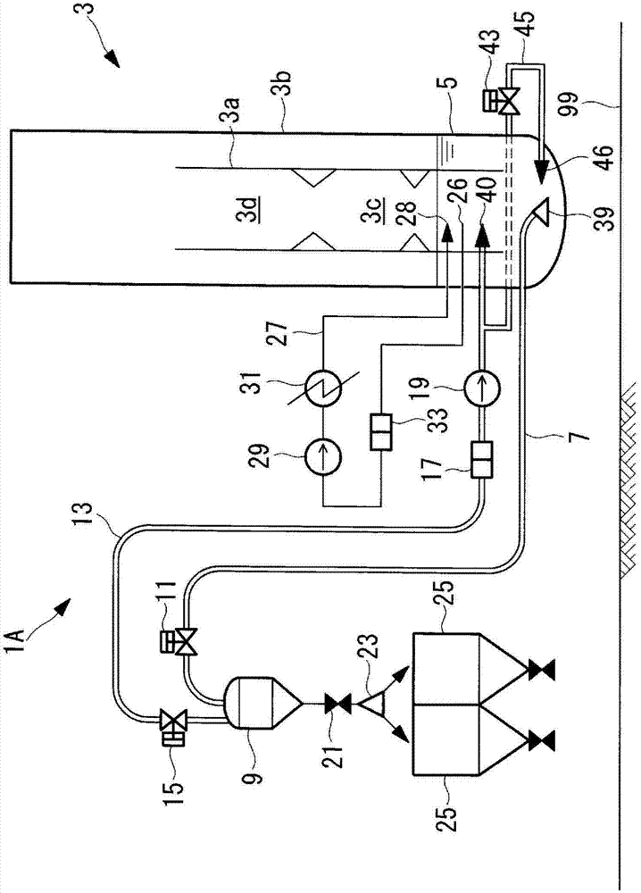
[0055] Below, use figure 1 The first embodiment of the present invention will be described.

[0056] figure 1 The slag discharge processing system 1A suitable for the coal gasification power plant (gasification power plant) which performs coal gasification combined power generation (IGCC: Integrated Coal Gasification Combined Cycle) is shown in .

[0057] The coal gasification power plant includes: a coal gasification device (gasification device) that gasifies coal powder (fine powder raw material) obtained by pulverizing coal (carbonaceous solid) with a mill or the like; a gas turbine (not shown), It is driven by combustion gas using combustible gas refined by the coal gasification device; a waste heat boiler (HRSG: Heat Recovery Steam Generator, not shown) that generates steam by passing the exhaust gas of the gas turbine; a steam turbine (not shown) is driven by steam generated by the exhaust gas boiler; and an electric generator (not shown) is powered by a gas turbine ...

no. 2 approach

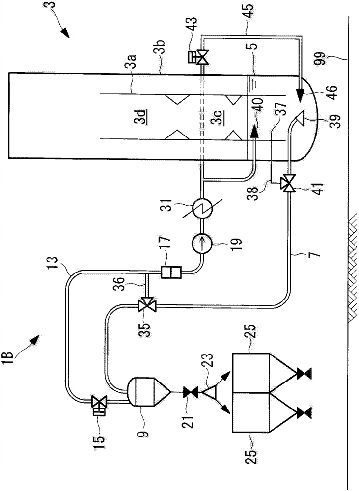
[0089] Next, use figure 2 A second embodiment of the present invention will be described.

[0090] In addition, the same code|symbol is attached|subjected to the same part as said 1st Embodiment, and detailed description is abbreviate|omitted.

[0091] The present embodiment is different in that the slag discharge line 7 and the water injection line 13 have the function of the cooling water circulation line 27 described in the first embodiment. thereby. In this embodiment, if figure 2 shown, omitted figure 1 Cooling water circulation line 27 is shown.

[0092] A bypass three-way valve (water flow direction switching mechanism) 35 is provided on the slag discharge line 7 . A bypass line 36 is connected to the bypass three-way valve 35 . The bypass line 36 connects the midway position of the slag discharge line 7 and the midway position of the water injection line 13 . The flow of cooling water directed from the slag hopper 5 to the slag discharge line 7 is switched by...

no. 3 approach

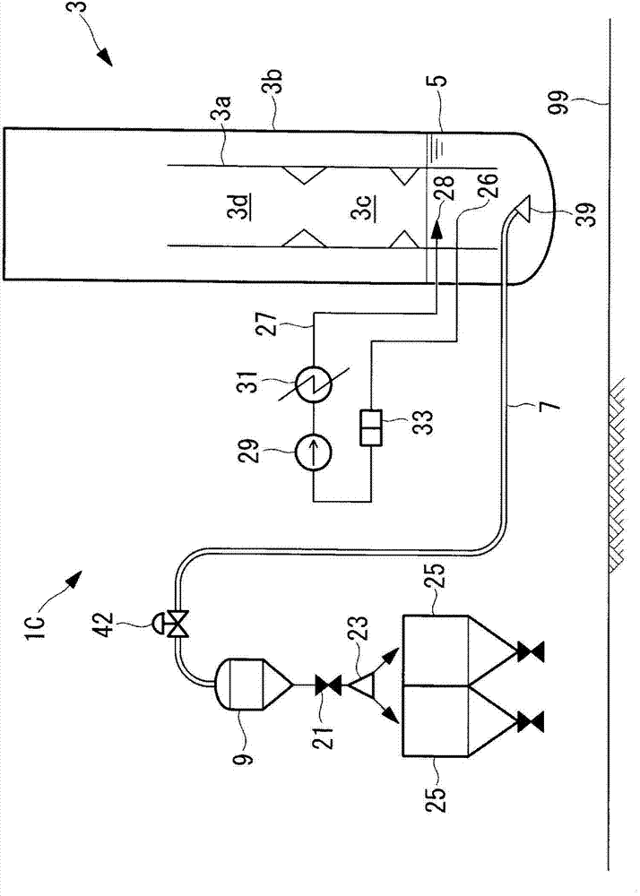
[0109] use image 3 , the third embodiment of the present invention will be described.

[0110] It should be noted that, for the above-mentioned first embodiment related figure 1 The same symbols are assigned to the same parts, and detailed description thereof will be omitted.

[0111] In the above-mentioned first embodiment and second embodiment, the following method is adopted, that is, the cooling water is injected into the slag hopper 5 from the water injection line 13 by the water injection pump 19, and the cooling water directed toward the lock hopper 9 is formed in the slag discharge line 7. However, in this embodiment, the flow of cooling water is formed in the slag discharge line 7 by using the pressure inside the gasifier 3 in a pressurized state without using the water injection pump 19 .

[0112] Such as image 3 shown, with the first embodiment of the figure 1 In comparison, they are the same in that the slag discharge line 7 is provided, but differ in that ...


PUM


Abstract

Provided is a slag discharge system with which, when installing the slag discharge system, it is possible to reduce height from a plant installation surface to a top portion of a gasification furnace. This slag discharge system (1A) comprises: a gasification furnace (3) which thermally decomposes and gasifies a fine powder material composed of a carbonaceous solid; a slag hopper (5) which is disposed on a base portion of the gasification furnace (3), receives slag generated from the fine powder material and in which cooling water is retained; a lock hopper (9) which temporarily retains the slag outside the gasification furnace (3) system; and a slag discharge line (7) which is communicated from the slag hopper (5) to the lock hopper (9). The lock hopper (9) is disposed to a side of the gasification furnace (3), and the slag discharge system (1A) is provided with a water flow forming means for forming a flow of the cooling water by which the slag is guided to the lock hopper (9) within the slag discharge line (7).

Description

technical field [0001] The present invention relates to a slag discharge system of a gasification furnace for gasifying fine powder raw materials such as coal powder composed of carbonaceous solids (biomass fuels such as coal and wood pellets, petroleum coke, etc.), and a gasification system equipped with the slag discharge system. device and gasification power generation device. Background technique [0002] In a gasifier that generates combustible gas by thermally decomposing fine powder raw materials made of carbonaceous solids, the ash content of these raw materials is melted and deposited as slag at the bottom of the gasifier. In order to store the slag, a water tank for storing cooling water is provided, and the slag is rapidly cooled by the cooling water, crushed and solidified. In this way, the slag accumulated in the gasifier water tank in a solidified state is discharged out of the system of the gasifier through the lock hopper. Since slag has a larger density di...

Claims


Application Information

Patent Timeline
IPC IPC(8): C10J3/46
CPCC10J3/72F02C3/28C10J2300/165C10J3/526Y02E20/18
Inventor 田泽直行吉田斋臣
Owner MITSUBISHI POWER LTD
Why Eureka
Try Eureka