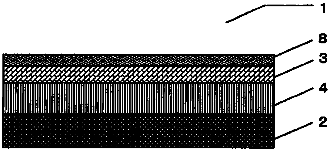
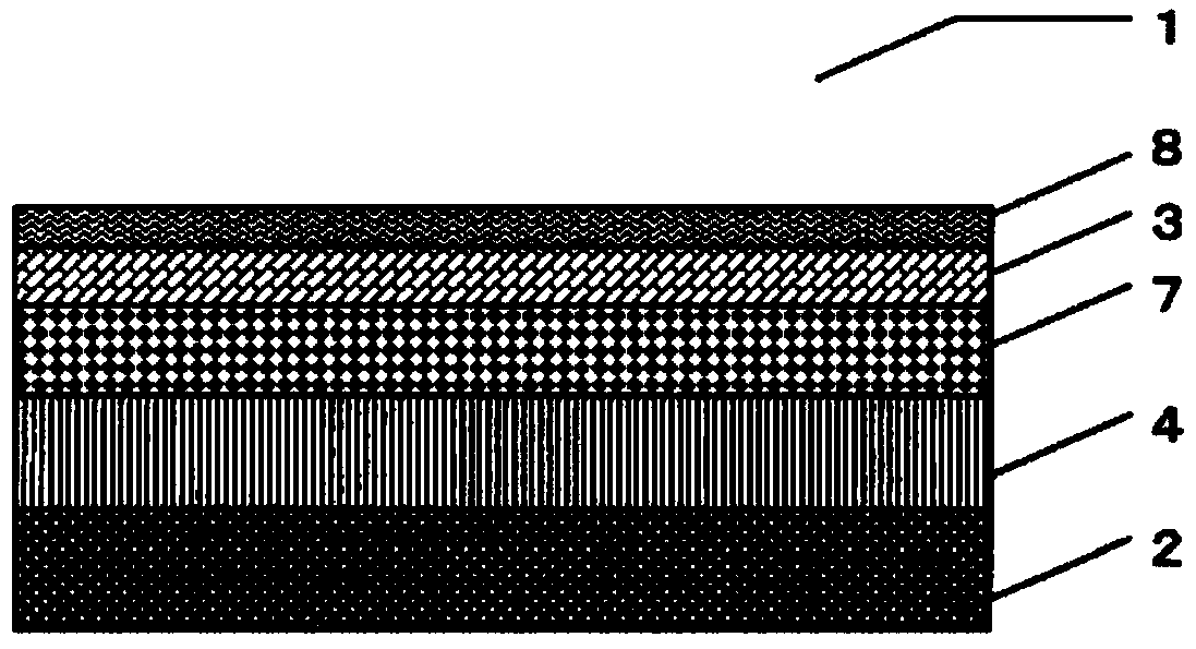
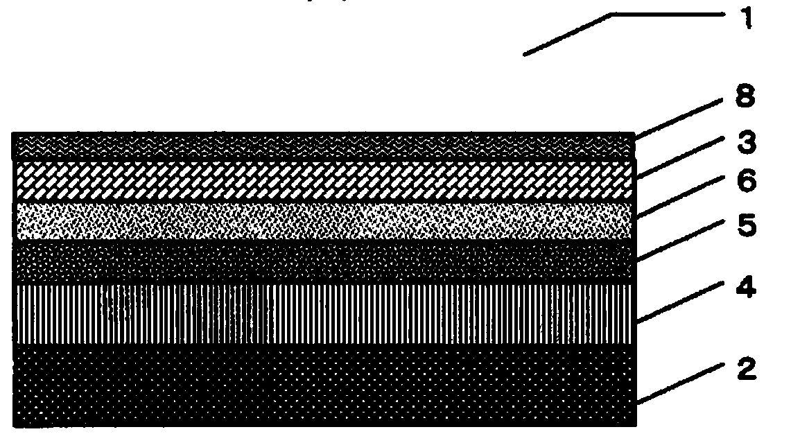
Method for producing antireflection film, antireflection film, polarizing plate, and image display device
An anti-reflective film and a technology for its manufacturing method are applied in the directions of polarizing elements, optics, instruments, etc., which can solve problems such as poor adhesion, shrinkage of transparent film substrates, and decreased anti-fouling properties, and achieve excellent scratch resistance and Effect of antifouling property and excellent antireflection characteristics
- Summary
- Abstract
- Description
- Claims
- Application Information
AI Technical Summary
Problems solved by technology
Method used
Image

Examples
preparation example Construction
[0055] (Preparation of composition for forming low refractive index layer)
[0056] The composition for forming a low refractive index layer is obtained by homogeneously mixing the fluorine-containing compound, fine particles, binder resin, and preferably used fluorine-containing polymer or various additives described later, and dissolving it in a solvent if necessary. while preparing.
[0057] The composition for forming a low refractive index is preferably liquid dissolved in a solvent in consideration of productivity. The viscosity of the liquid low-refractive index layer-forming composition is not particularly limited as long as a coating film can be formed on the surface of the transparent substrate by the coating method described later.
[0058] (formation of coating film)
[0059] The coating film is formed on the surface of the transparent base material so that the thickness after curing becomes a predetermined thickness described below. The composition for forming a...
Embodiment
[0212] Hereinafter, although an Example demonstrates this invention in detail, this invention is not limited to these Examples.
[0213] (Evaluation method)
[0214] 1. Minimum reflectance (evaluation of anti-reflection characteristics)
[0215] For the anti-reflection film obtained in each embodiment and comparative example, a black adhesive tape for preventing the back reflection of the film is pasted on the side of the transparent substrate where the low-refractive index layer is not provided, and from the surface of the low-refractive index layer, use The reflectance was measured with a spectrometer ("UV-2550 (model)": manufactured by Shimadzu Corporation) equipped with a regular reflection measuring device at 5 degrees, and the minimum value in the wavelength region of 380 to 780 nm was taken as the minimum reflectance. The smaller the minimum reflectance, the better the antireflection property of the antireflection film.
[0216] 2. Evaluation of coated surface
[021...
preparation example 1
[0248] Preparation Example 1: Preparation of Low Refractive Index Layer Forming Composition 1
[0249] The components of the following composition were mixed in the following mass ratio, and the composition 1 for low-refractive-index layer formation was prepared.
[0250] Composition 1 for forming a low refractive index layer
[0251] Pentaerythritol triacrylate (PETA): 0.10 parts by mass
[0252] Fluorinated compounds *1 : 1.23 parts by mass
[0253] Hollow Silica Particle Dispersion *2 : 6.69 parts by mass
[0254] Solid silica particle dispersion *3 : 0.74 parts by mass
[0255] Fluoropolymer *4 : 2.79 parts by mass
[0256] Fluorinated monomer *5 : 2.23 parts by mass
[0257] photopolymerization initiator *6 : 0.08 parts by mass
[0258] Methyl isobutyl ketone: 57.03 parts by mass
[0259] Propylene glycol monomethyl ether acetate: 29.1 parts by mass
[0260] *1, "X-71-1203M (trade name)": Shin-Etsu Chemical Co., Ltd., 20% by mass solution (solvent: methyl is...
PUM
| Property | Measurement | Unit |
|---|---|---|
| surface roughness | aaaaa | aaaaa |
| particle size | aaaaa | aaaaa |
| thickness | aaaaa | aaaaa |
Abstract
Description
Claims
Application Information