CO2 absorption refrigerator driven by solar energy
An absorption refrigerator, solar energy technology, applied in the field of refrigerators in the field of refrigeration technology, can solve problems such as restricting the development of refrigeration technology and demanding compressor requirements, and achieve the effects of compact structure, environmental friendliness, and good application prospects.
- Summary
- Abstract
- Description
- Claims
- Application Information
AI Technical Summary
Problems solved by technology
Method used
Image

Examples
Embodiment 1
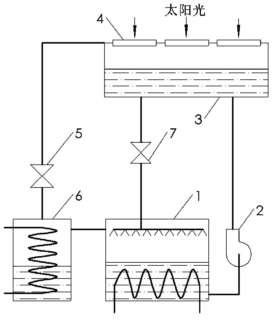
[0029] figure 1 Is a solar-driven CO of the present invention 2 The schematic diagram of the structure of embodiment 1 of the absorption chiller; it can be seen from the figure that the solar-powered CO of this embodiment 1 2 Absorption refrigerator, which includes:
[0030] The absorber 1, the booster pump 2, the solar generator 3, the decompression element 5 and the evaporator 6, which are connected in sequence and form a refrigeration circuit, and the connecting pipe connected between the absorber 1 and the solar generator 3 On the flow control valve 7 on the road, the evaporator 6 is connected to the absorber 1; the upper end of the solar generator 3 is equipped with a light-transmitting element 4; the inlet of the booster pump 2 is connected to the absorber 1, and the booster The outlet of the pressure pump 2 is connected to the generator 3; a flowing working medium circulates in the refrigeration circuit; a light-transmitting element 4 is installed at the upper end of the so...
Embodiment 2
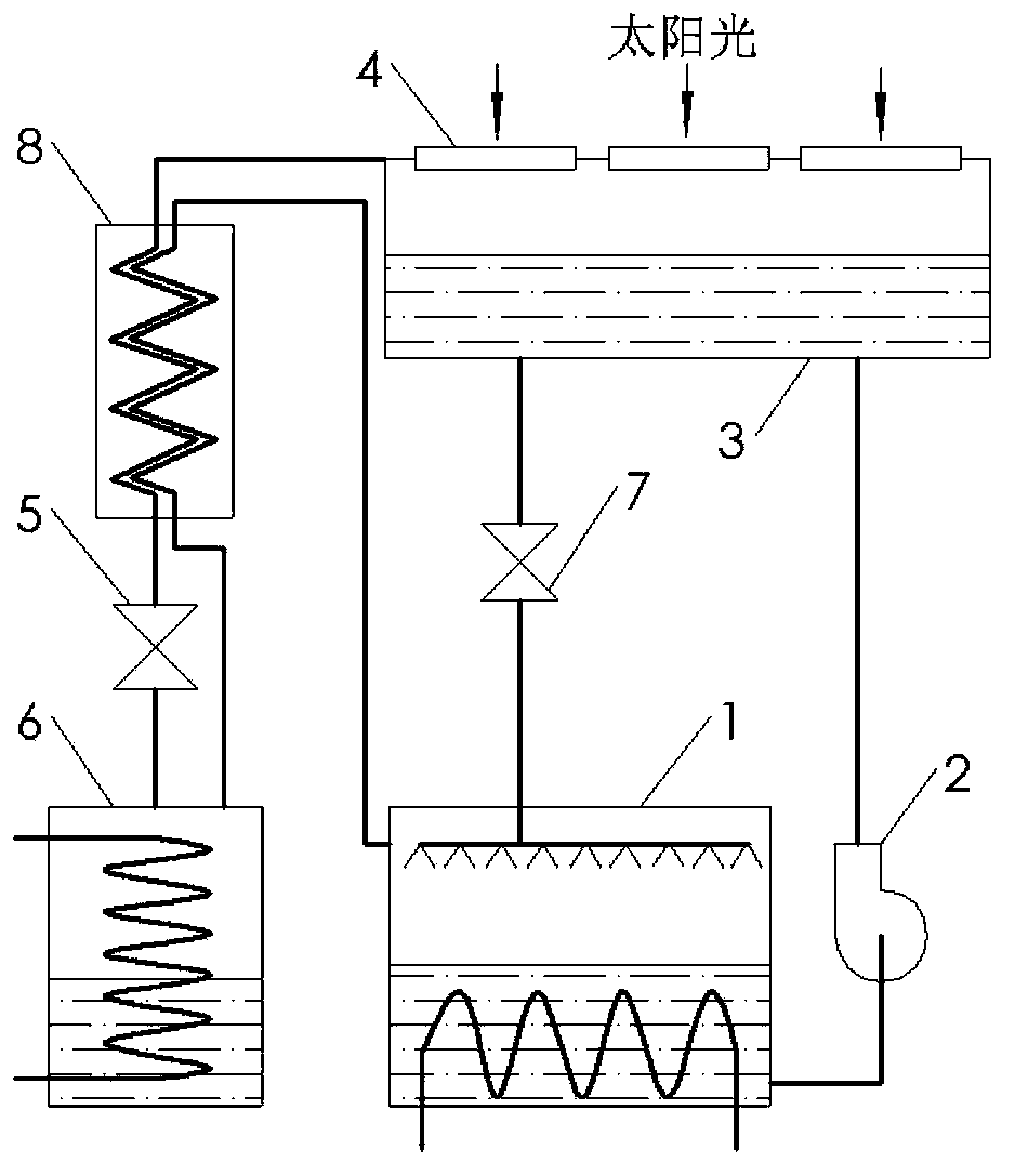
[0033] figure 2 Is another solar-driven CO of the present invention 2 Schematic diagram of the structure of an absorption chiller (Example 2). It can be seen from the figure that the difference between Embodiment 2 and Embodiment 1 is that a regenerator 8 is added, that is, the regenerator 8 is installed on the connecting pipeline between the solar generator 3 and the pressure reducing element 5; The two ends of the regenerator 8 are also communicated with the evaporator 6 and the absorber 1 respectively. Because of CO 2 The critical point temperature of the evaporator is relatively low. If it is throttling and cooling at room temperature, it is difficult to produce a better cooling effect. Therefore, in this embodiment, the temperature and pressure from the evaporator 6 are relatively low. 2 Flow through the regenerator 8, so that the high-pressure CO 2 The gas is cooled below room temperature and then expanded under reduced pressure, so that CO 2 Achieve better cooling effect...
Embodiment 3
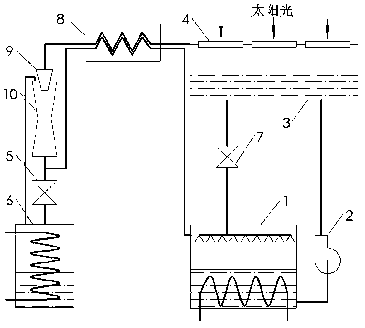
[0035] image 3 Is another solar-driven CO of the present invention 2 Schematic diagram of the structure of an absorption refrigerator (embodiment 3); the structure of this embodiment basically adds a regenerator 8, a nozzle 9 and an ejector 10 in the structure of the embodiment 1; the regenerator 8, the nozzle 9 and the ejector The evaporator 10 is connected to the connecting pipeline from the solar generator 3 to the pressure reducing element 5 in sequence, and the inlet of the ejector 10 is connected to the evaporator 6; The decompression element 5 is in communication with the absorber 1. Because the cooling efficiency of the simple throttling and decompression process is low, the nozzle 9 and the ejector 10 are sequentially installed on the connecting pipeline between the generator 3 and the decompression element 5 in this embodiment; high-pressure CO 2 After the gas is cooled by the regenerator 8, the gas first flows through the nozzle 9, and then CO 2 The temperature of t...
PUM
 Abstract
Description
Claims
Application Information
 - R&D
- Intellectual Property
- Life Sciences
- Materials
- Tech Scout
- Unparalleled Data Quality
- Higher Quality Content
- 60% Fewer Hallucinations
Browse by: Latest US Patents, China's latest patents, Technical Efficacy Thesaurus, Application Domain, Technology Topic, Popular Technical Reports.
© 2025 PatSnap. All rights reserved.Legal|Privacy policy|Modern Slavery Act Transparency Statement|Sitemap|About US| Contact US: help@patsnap.com