Method and equipment for separating methane from synthesis gas

A separation equipment, synthesis gas technology, applied in lighting and heating equipment, cold treatment separation, refrigeration and liquefaction, etc., can solve problems such as high cost and low efficiency, achieve high effectiveness, reduce equipment costs, and improve effectiveness.

Inactive Publication Date: 2014-05-07
LINDE AG
View PDF7 Cites 3 Cited by
  • Summary
  • Abstract
  • Description
  • Claims
  • Application Information

AI Technical Summary

Problems solved by technology

[0005] Especially in the case where a liquid refrigerant or a corresponding two-phase mixture is required in the corresponding equipment, the known methods have proven to be inefficient, since the production and / or treatment of such mixtures i.e. compression, cooling, depressurization and / or delivery usually comes with considerable cost

Method used


Image

  • Method and equipment for separating methane from synthesis gas
  • Method and equipment for separating methane from synthesis gas
  • Method and equipment for separating methane from synthesis gas

Examples


Embodiment Construction

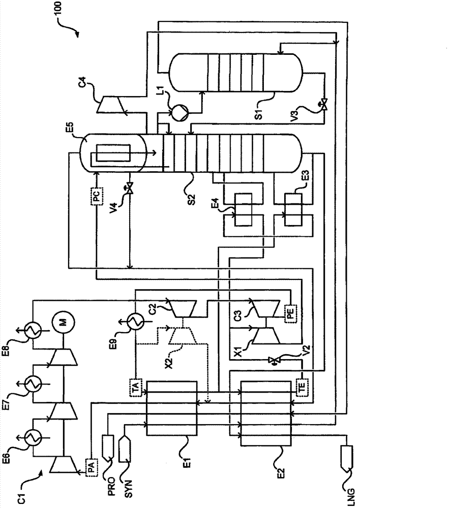
[0044] figure 1 Shown is a plant not according to the invention for the separation of methane from methane-containing synthesis gas. The device is denoted as a whole by the reference number 100 .

[0045] The plant 100 has a first separation column S1 and a second separation column S2. The first separation column S1 and the second separation column S2 work under different pressures. The pressure difference is, for example, 5 to 30 bar, especially 10 to 20 bar. The pressure of the second separation column S2 can be limited to 25 to 30 bar to ensure a pressure difference between the gaseous and liquid phases of at least 240 kg / m 3 , especially at least 270kg / m 3 .

[0046] The methane-containing synthesis gas SYN is cooled in the first heat exchanger E1 to a temperature of, for example, -60 to -110° C., in particular -80 to -95° C., and in the second heat exchanger E2 to, for example, -120° C. to a temperature of -170° C., especially -130 to -160° C., which is then fed to ...


PUM


Abstract

The invention proposes a method for separating methane (LNG) from a methane-containing synthesis gas (SYN) in low temperature separation equipment (10). The low temperature separation equipment includes a refrigerant circuit having at least one expander (X1) and at least one separating column (S2) having a condenser (E5), and A portion of compressed and cooled refrigerant from the refrigerant circuit is supplied to the at least one expander (X1) and the condenser (E5) respectively. A primary portion of the refrigerant which is cooled to an intermediate temperature (TI) from a starting temperature (TA) is supplied to the at least one expander (X1). A secondary portion of the refrigerant which is firstly cooled to an intermediate temperature (TI) from a starting temperature (TA) and then cooled to a lower final temperature (TE) is supplied to the condenser (E5). The invention also relates to equipment (10, 11, 12) used for implementing the method according to the invention.

Description

technical field [0001] The invention relates to a method for separating methane from methane-containing synthesis gas and corresponding equipment. Background technique [0002] The synthesis gas produced by known methods from coal, oil or natural gas usually contains methane in an amount of usually 3 to 30% by volume and smaller amounts of other components in addition to the desired components hydrogen and carbon monoxide after removal of acid gases . Examples are nitrogen, oxygen, argon, carbon dioxide and ethane each having less than 1% by volume. Since the presence of methane in the synthesis gas is particularly undesirable, it is usually separated off. [0003] Methane can be separated from methane-containing synthesis gas in a cryogenic separation plant. The device can be operated with a refrigeration circuit in which the refrigerant is compressed, for example in multiple stages and with intercooling and aftercooling. The compressed refrigerant can then be cooled in...

Claims


Application Information

Patent Timeline
Patent Type & Authority Applications(China)
IPC IPC(8): F25J3/00
CPCF25J3/00F25J3/02F25J3/0223F25J3/0233F25J3/0271F25J2200/40F25J2200/72F25J2200/78F25J2205/30F25J2215/02F25J2215/04F25J2230/08F25J2245/02F25J2270/12F25J2270/14F25J2270/16F25J2270/42F25J2290/34
Inventor H·施密特
Owner LINDE AG
Why Eureka
Try Eureka