Electric-heating air-circulating-type drying box

An air circulation and electric heating technology, applied in the field of drying boxes, can solve the problems of air turbulence, no mention of heat preservation and fireproof and heat insulation functions, inconvenient maintenance and replacement, etc., to achieve uniform and fast heating, and avoid uneven heating , the effect of controllable heat size

Active Publication Date: 2014-05-07
HARBIN ENG UNIV
View PDF4 Cites 3 Cited by
  • Summary
  • Abstract
  • Description
  • Claims
  • Application Information

AI Technical Summary

Problems solved by technology

[0002] The traditional large-scale drying box has a single structure and uses raw coal for heating, which has low thermal efficiency and is likely to cause environmental pollution and waste of resources
Moreover, the existing large-scale drying boxes generally do not mention the functions of heat preservation and fire prevention and heat insulation, which increases safety hazards
Generally, the control system of large-scale dryers is located on the side of the box, which is not convenient for maintenance and replacement, and the control is simple, which cannot meet the needs of actual fine production
The air flow in the box is generally blown by a high-power axial flow fan, or a single axial flow fan blows from the top down, the wind direction is difficult to control, and it is easy to generate air turbulence and air dead angle

Method used


Image

  • Electric-heating air-circulating-type drying box
  • Electric-heating air-circulating-type drying box
  • Electric-heating air-circulating-type drying box

Examples


Embodiment Construction

[0015] The present invention is described in more detail below in conjunction with accompanying drawing example:

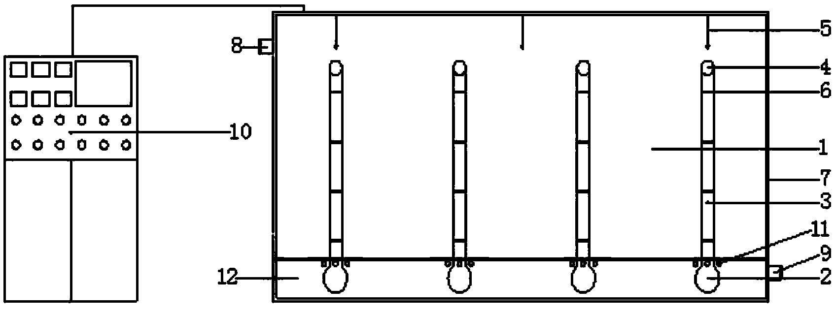
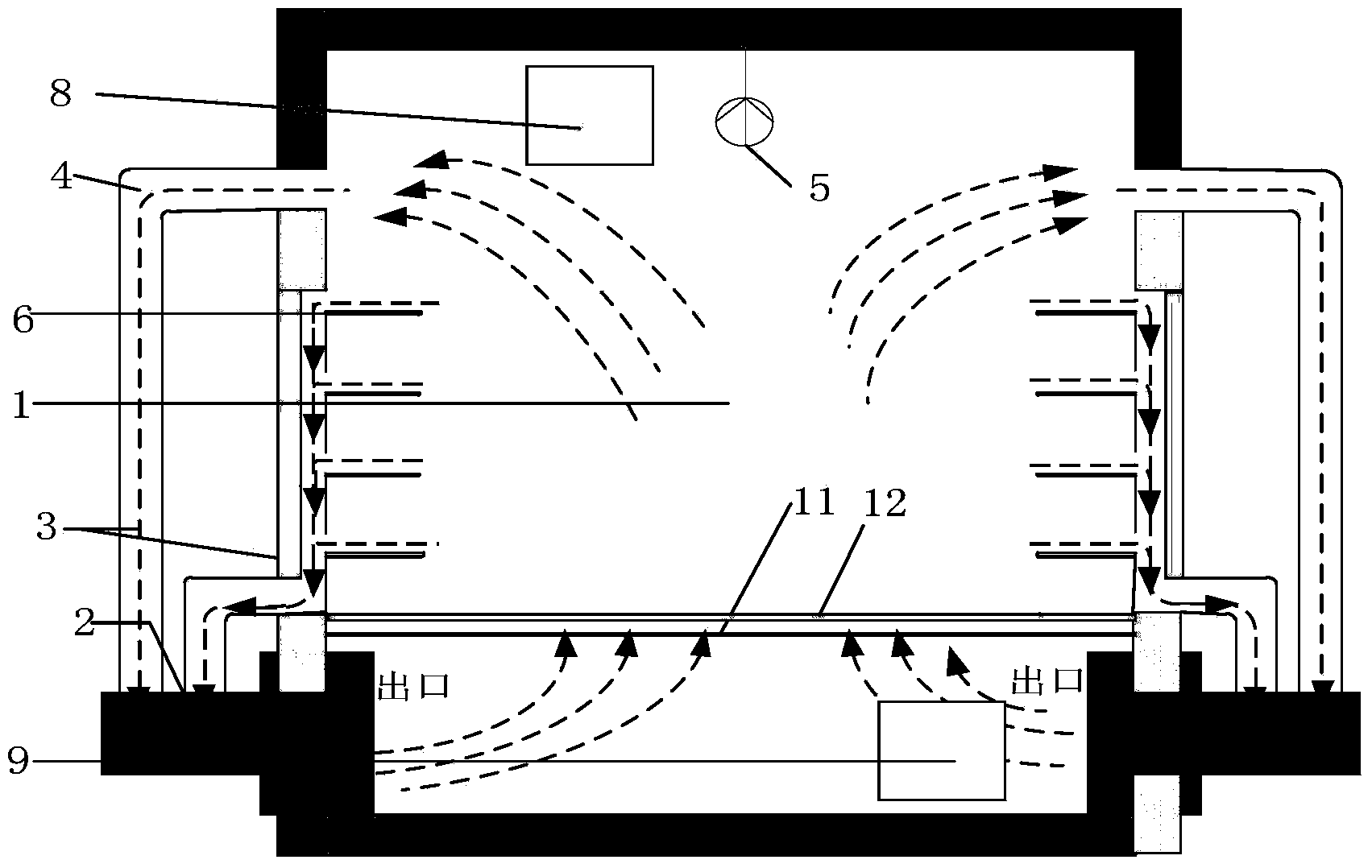
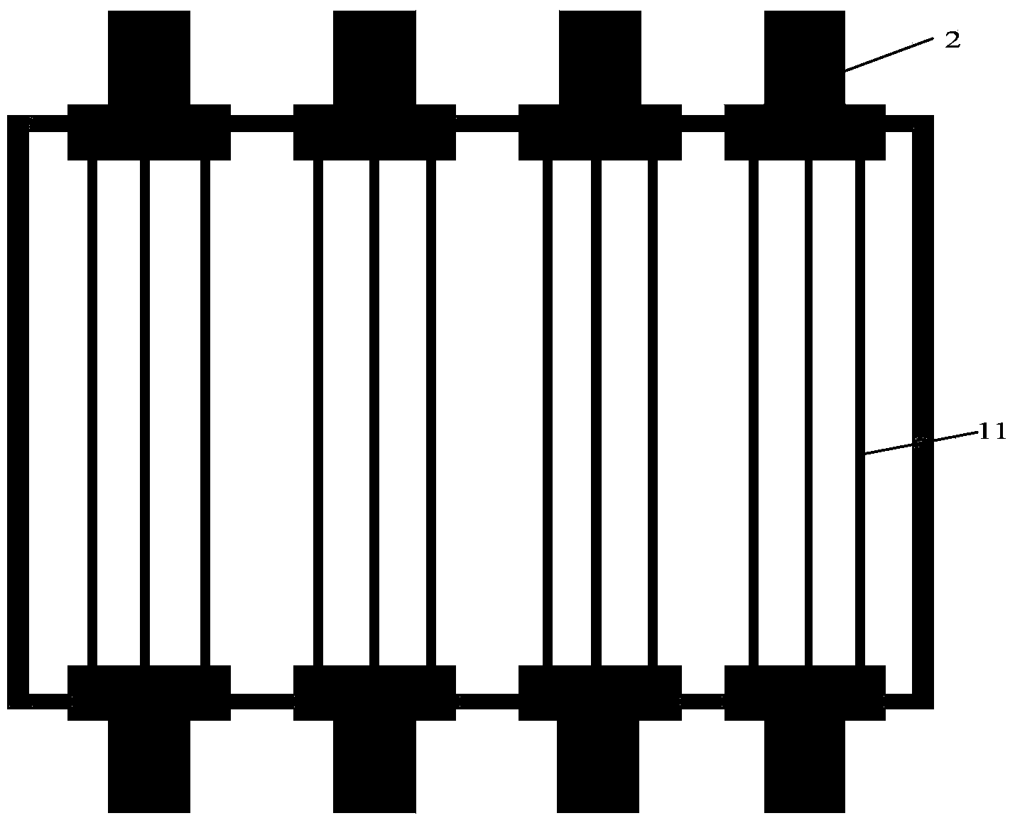
[0016] combine Figure 1~3 , the drying box is mainly composed of box 1, axial flow fan 2, return pipe 3, connecting elbow 4, sensor 5, swing plate 6, door 7, air outlet 8, air inlet 9, control cabinet 10, heating rod 11 , 12 metal sieve plates.

[0017] It works like this:

[0018] One end of the axial flow fan 2 is embedded in the box body 1, and the other end is rotatably connected to the return pipe 3 through the elbow 4, and the other end of the return pipe 3 is connected to the box body 1 through the elbow 4, and each connection part is sealed deal with;

[0019] Install the sensor 5 on the upper part of the box body 1 and connect it tightly;

[0020] Fix the swing plate 5 in the box through the slideway.

[0021] Install a one-way fan blade axial flow fan at the air outlet 8 and the air inlet 9, and fix it.

[0022] Fix the heating rod 11 under the me...


PUM


Abstract

The invention provides an electric-heating air-circulating-type drying box which comprises a box body, a heating bar and an air circulating unit. The upper end of the box body is provided with an air outlet, the lower end of the box body is provided with an air inlet, the air outlet and the air inlet are provided with a first axial flow fan and a second axial flow fan respectively, sliding channels are arranged in the box body, swinging plates are arranged on the sliding channels, the air circulating unit comprises a first return pipeline, a second return pipeline, a third axial flow fan and a fourth axial flow fan, the side face of the box body is sequentially provided with an upper air outlet hole, a lower air outlet hole and an air inlet hole from top to bottom, the upper air outlet hole is located between the inner wall of the upper portion of the box body and the uppermost-layer sliding channel, the lower air outlet hole is located below the bottommost-layer sliding layer, and the air inlet hole is located below the lower air outlet hole. The drying box is safe and quick to use and easy to control; the box body is made of stainless steel; a control system is arranged outside separately and is convenient to repair and maintain; the double-channel axial fans are used, an air flow system is manufactured manually, and heating efficiency is doubled.

Description

technical field [0001] The invention relates to a drying box, in particular to a drying box for agricultural production. Background technique [0002] The traditional large-scale drying box has a single structure and uses raw coal for heating, which has low thermal efficiency and is likely to cause environmental pollution and waste of resources. Moreover, the existing large-scale drying boxes generally do not mention heat preservation and fire-proof and heat-insulating functions, which increases potential safety hazards. Generally, the control system of large-scale dryers is located on the side of the cabinet, which is not convenient for maintenance and replacement, and the control is simple, which cannot meet the needs of actual fine production. The air flow in the box is generally blown by a high-power axial fan, or a single axial fan is blown from the top, the wind direction is difficult to control, and it is easy to generate air turbulence and air dead ends. Contents ...

Claims


Application Information

Patent Timeline
IPC IPC(8): F26B9/06F26B21/04F26B23/06F26B25/12
Inventor 李冰费浚纯邢博闻张兰勇李相武
Owner HARBIN ENG UNIV
Why Eureka
Try Eureka