Method and device for calibrating absolute response rate of terahertz quantum-well detector

A terahertz detector technology, applied in the field of terahertz detectors, can solve the problems of low calibration accuracy, cumbersome calibration process, and low calibration efficiency, and achieve improved calibration accuracy and calibration efficiency, accurate calibration results, and extensive The effect of applicability

Active Publication Date: 2014-05-07
SHANGHAI INST OF MICROSYSTEM & INFORMATION TECH CHINESE ACAD OF SCI
View PDF3 Cites 10 Cited by
  • Summary
  • Abstract
  • Description
  • Claims
  • Application Information

AI Technical Summary

Problems solved by technology

[0005] In view of the shortcomings of the prior art described above, the purpose of the present invention is to provide a method and device for calibrating the absolute responsivity of a terahertz quantum we...

Method used


Image

  • Method and device for calibrating absolute response rate of terahertz quantum-well detector
  • Method and device for calibrating absolute response rate of terahertz quantum-well detector
  • Method and device for calibrating absolute response rate of terahertz quantum-well detector

Examples


Embodiment 1

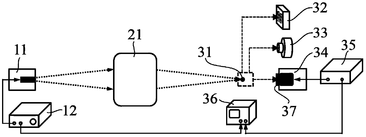
[0054] The present invention provides a device for calibrating the absolute responsivity of a terahertz quantum well detector, please refer to figure 1 , shows the structure and optical path schematic diagram of the device, including at least: a driving power supply 12, a single-frequency laser source 11, an optical mirror 21, a terahertz array detector 32, a terahertz power meter 33, a current amplifier 35 and an oscilloscope 36. figure 1 It also shows that the calibrated terahertz quantum well detector 34 is located in the optical path during the calibration process and the window 37 installed on the cooling dewar of the terahertz quantum well detector 34 . The function of the window 37 is to transmit and converge the terahertz light on the sensitive surface of the terahertz quantum well detector 34 .

[0055] Such as figure 1 As shown, the single-frequency laser source 11 is used as a calibration laser source, which is connected to the driving power supply 12 and used to r...

Embodiment 2

[0064] The present invention also provides a method for calibrating the absolute responsivity of a terahertz quantum well detector. The specific process of the calibration method of the present invention will be described in detail below in conjunction with the device and parameters described in Embodiment 1, which at least includes the following steps:

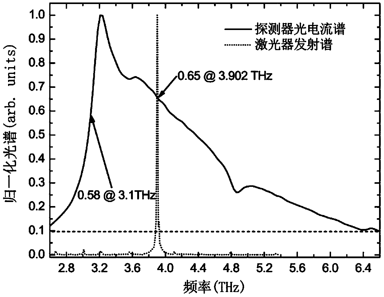
[0065] Step S1: using the driving power supply 12 to output a square wave signal with a period of t to drive the single-frequency laser source 11, so that the single-frequency laser source 11 radiates a terahertz signal whose period is consistent with the driving signal and whose frequency is f laser. In this embodiment, the single-frequency laser source 11 takes a terahertz quantum cascade laser as an example, the square wave signal t=5ms, and the laser frequency f=3.902THz output by the terahertz quantum cascade laser.

[0066] Step S2: Adjust the optical mirror 21 to a preset position, so that the terahertz laser reaches t...


PUM

PropertyMeasurementUnit
Diameteraaaaaaaaaa
Thicknessaaaaaaaaaa

Abstract

The invention discloses a method and a device for calibrating an absolute response rate of a terahertz quantum-well detector. The device at least comprises a driving power supply, a single-frequency laser source, an optical lens, a terahertz array detector, a terahertz power meter, a current amplifier and an oscilloscope. The calibrating method adopts the single-frequency laser source detected by using power as a calibration light source to acquire an absolute response rate of the detector in the laser frequency; and the method uses a normalization photocurrent spectrum of the detector to further calculate and acquire the absolute response rate of the detector in any position with a detectable frequency. According to the method, the cyclic output single-frequency laser source is directly used as the calibration light source; and the terahertz array detector and the power meter are directly used for measuring and acquiring an incident power of the calibrated detector, so that the influence caused due to background light and water vapor absorption in a conventional calibration method is greatly reduced; the complex calculation of various spectrum integrations is avoided; the whole calibration process is simple; small error is introduced; and the method is wide in applicability.

Description

technical field [0001] The invention belongs to the technical field of terahertz detectors, and relates to a method and a device for calibrating the absolute responsivity of a terahertz quantum well detector. Background technique [0002] Terahertz quantum well detector is a semiconductor detector with fast response speed, narrow response spectrum, small size and easy integration. It is a very important type of detector in terahertz application technology. This type of detector was successfully developed by Canadian scientists for the first time in 2004. It has been widely studied due to its simple material structure and high responsivity. Currently, the detectable frequency range of the device mainly covers the 2-7THz frequency band. Laser sources in the 2-7THz frequency band mainly include terahertz quantum cascade lasers and carbon dioxide gas lasers. Due to their long cavity lengths, carbon dioxide lasers produce lasers with good single-frequency performance and high bea...

Claims


Application Information

Patent Timeline
IPC IPC(8): G01J5/20
CPCG01J1/4257G01J1/08G01J1/4228G01J3/42G01J2001/083
Inventor 谭智勇曹俊诚顾立朱永浩
Owner SHANGHAI INST OF MICROSYSTEM & INFORMATION TECH CHINESE ACAD OF SCI
Why Eureka
Try Eureka