
Sample heating rack for microscope or analysis device using electron beam, and sample heating method using same

A technology of an analysis device and a heating method, which is applied to circuits, discharge tubes, electrical components, etc., can solve the problems of changes in the contrast of observed images, inability to completely suppress contamination, and reduction in element analysis accuracy, and achieve thermal drift suppression and high precision. Image observation, the effect of preventing the growth of contamination

Active Publication Date: 2017-04-05
JFE STEEL CORP
View PDF12 Cites 0 Cited by
  • Summary
  • Abstract
  • Description
  • Claims
  • Application Information

AI Technical Summary

Problems solved by technology

[0002] In microscopes or analysis devices using electron beams, such as scanning electron microscopes, transmission electron microscopes, electron beam microanalyzers, and Auger electron spectrometers, which are used to evaluate the microstructure of materials, there are profound problems as follows: Carbon contamination (hereinafter referred to as "contamination") is generated on the surface of the sample due to the interaction of the incident electron beam with the contamination substances such as hydrocarbons on the surface and surroundings of the evaluation sample, which changes the contrast of the observed image, or makes the carbon as the Reduced analytical precision for the represented elements
However, in the method of ultra-vacuumizing the sample chamber, it is necessary to perform a baking operation of heating the surrounding of the sample chamber at 100 to 200°C for several hours to several days, so there are many restrictions on the equipment as follows : The materials used for the device, the spectrometer used for the analysis, the electron gun must be made to withstand the baking operation and the maintenance of the ultra-high vacuum
In addition, since this method does not directly remove the pollutants existing on the surface of the sample, there is a problem that the generation of contamination cannot be completely suppressed by this method alone.
In addition, the method of sputtering using Ar ions, etc. has the following limitations: it cannot be applied unless an ion gun for sputtering is installed, and because it is accompanied by damage to the surface of the sample, it can only be applied to sputtering without damage. If image observation and elemental analysis of the sample surface are adversely affected
In addition, if it is not used in combination with the ultra-high vacuum of the sample chamber, even if it is temporarily removed by sputtering, re-adsorption of contaminant molecules will occur on the sample surface, so the growth of contamination cannot be completely prevented.

Method used


Image

  • Sample heating rack for microscope or analysis device using electron beam, and sample heating method using same
  • Sample heating rack for microscope or analysis device using electron beam, and sample heating method using same
  • Sample heating rack for microscope or analysis device using electron beam, and sample heating method using same

Examples


Embodiment 1

[0033] Use copper double-sided tape (copper-containing double-sided tape) to fix the ceramic PTC thermistor with a Curie temperature of 92°C, a working voltage of 100V, and a stable current of 32mA on the existing aluminum sample holder for scanning electron microscopes. Obtain the sample heating frame of the present invention, use copper adhesive tape to fix the nickel-chromium wire heater and thermocouple through insulation coating on the above-mentioned aluminum sample frame, and obtain the comparative sample heating frame that can carry out PID control, The following tests were carried out using the sample heating rack of the present invention and the heating rack for comparison.

[0034] On the heated portion of these sample heating racks, a silicon wafer, a commercially available, mirror-polished silicon wafer that was air-dried after washing with isopropanol for 10 minutes, was fixed with copper double-sided tape as a sample. The silicon wafer was set on a sample stage ...

Embodiment 2

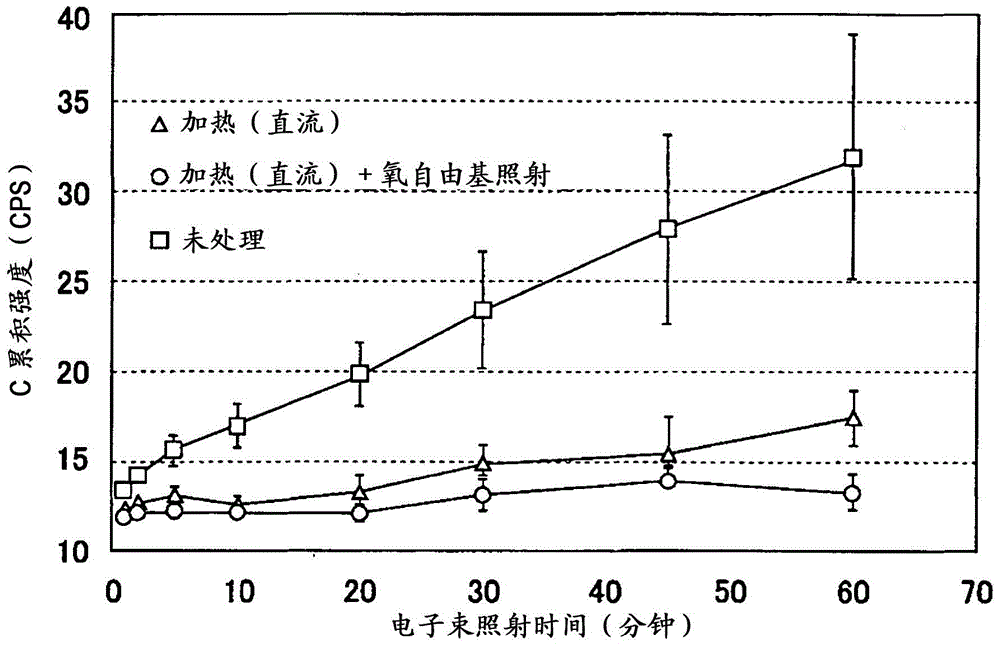
[0044] On the sample heating rack of the present invention, fix pure iron (commercially available plate-shaped standard sample: purity 99.9%) to replace the silicon wafer used in Example 1 as a sample, after heating, heating+oxygen free radicals In the irradiated and unheated untreated state, the amount of contamination on the sample surface (C accumulation intensity) was measured by changing the electron beam irradiation time. At this time, heating was performed under the same conditions as in Example 1, and oxygen radical irradiation was performed using a commercially available high-frequency plasma generator. In addition, the surface of pure iron is active, so it is easier to attach contamination than silicon wafers. When electron beams are irradiated for a long time, the analysis is hindered by contamination. Therefore, the contamination was measured up to the irradiation time of 60 minutes. Quantity changes over time. The measurement was performed under the same conditio...

Embodiment 3

[0048] Using the same method as in Example 1, a ceramic PTC thermistor with a Curie temperature of 92°C, a working voltage of 100V, and a stable current of 32mA was fixed to the existing scanning electron microscope with copper double-sided tape (copper-containing double-sided tape). The following tests were performed on the sample heating rack of the present invention obtained on an aluminum sample rack.

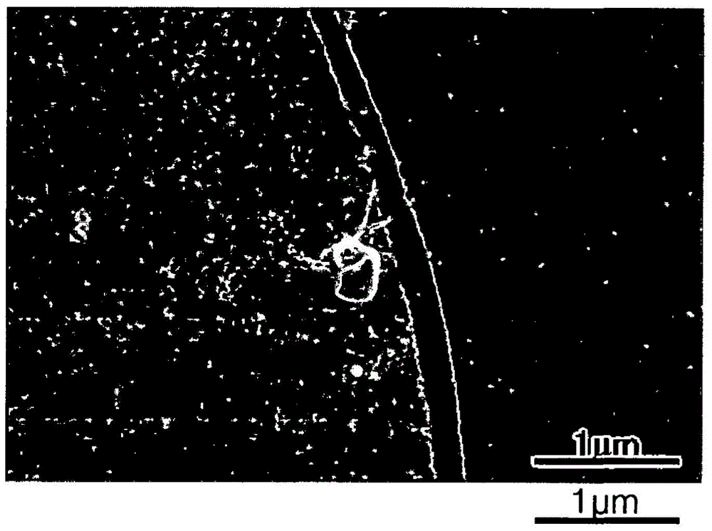
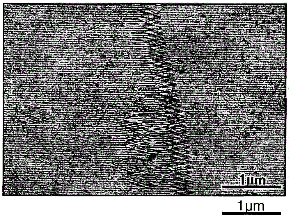
[0049] On the heating part of the sample heating rack, copper double-sided adhesive tape was used to fix an extremely low carbon steel plate as a sample. A dried commercially available ultra-low carbon steel sheet was set on a sample stage of a scanning electron microscope SUPRA55VP manufactured by Carl Zeiss, and the temperature was set at 92° C. to perform image observation. At this time, DC voltage and AC voltage were supplied to the sample heating rack through the current introduction terminal attached to the front surface of the SUPRA55VP sample stage, and image observ...


PUM


Abstract

The invention provides a sample heating holder for electron beam microscopes or analyzers and a sample heating method using the holder, which can prevent stably the occurrence of contaminants on the sample surface without entailing ultrahigh vacuum evacuation or destructing the sample surface. The sample heating holder for an electron beam microscope or analyzer has excellent performance in the suppression of the growth of carbon contaminations and the occurrence of a thermal drift during observation and analysis, and includes a positive temperature coefficient (PTC) thermistor as a heating element.

Description

technical field [0001] The present invention relates to a sample heating rack used in microscopes or analysis devices using electron beams, such as electron microscopes and electron beam microanalyzers, and to a sample heating method using the sample heating rack. Background technique [0002] In microscopes or analysis devices using electron beams, such as scanning electron microscopes, transmission electron microscopes, electron beam microanalyzers, and Auger electron spectrometers, which are used to evaluate the microstructure of materials, there are profound problems as follows: Carbon contamination (hereinafter referred to as "contamination") is generated on the surface of the sample due to the interaction of the incident electron beam with the contamination substances such as hydrocarbons on the surface and surroundings of the evaluation sample, which changes the contrast of the observed image, or makes the carbon as the The analytical precision of the represented elem...

Claims


Application Information

Patent Timeline
Patent Type & Authority Patents(China)
IPC IPC(8): H01J37/20
CPCH01J37/20H01J2237/022H01J2237/2001
Inventor 山下孝子野吕寿人关本光义渡边学贺嶋能久
Owner JFE STEEL CORP
Learn More