Diesel engine silencer of tension-free silencing chamber structure
A technology for diesel engines and anechoic chambers, which is applied to silencing devices, machines/engines, mechanical equipment, etc., can solve the problems of poor anti-vibration performance, high cost, and failure to meet the requirements of energy saving and consumption reduction, and achieves improved anti-vibration and anti-cracking. performance, maintain the effect of cooling and noise reduction, and facilitate the effect of production and assembly
- Summary
- Abstract
- Description
- Claims
- Application Information
AI Technical Summary
Problems solved by technology
Method used
Image
Examples
Embodiment 1
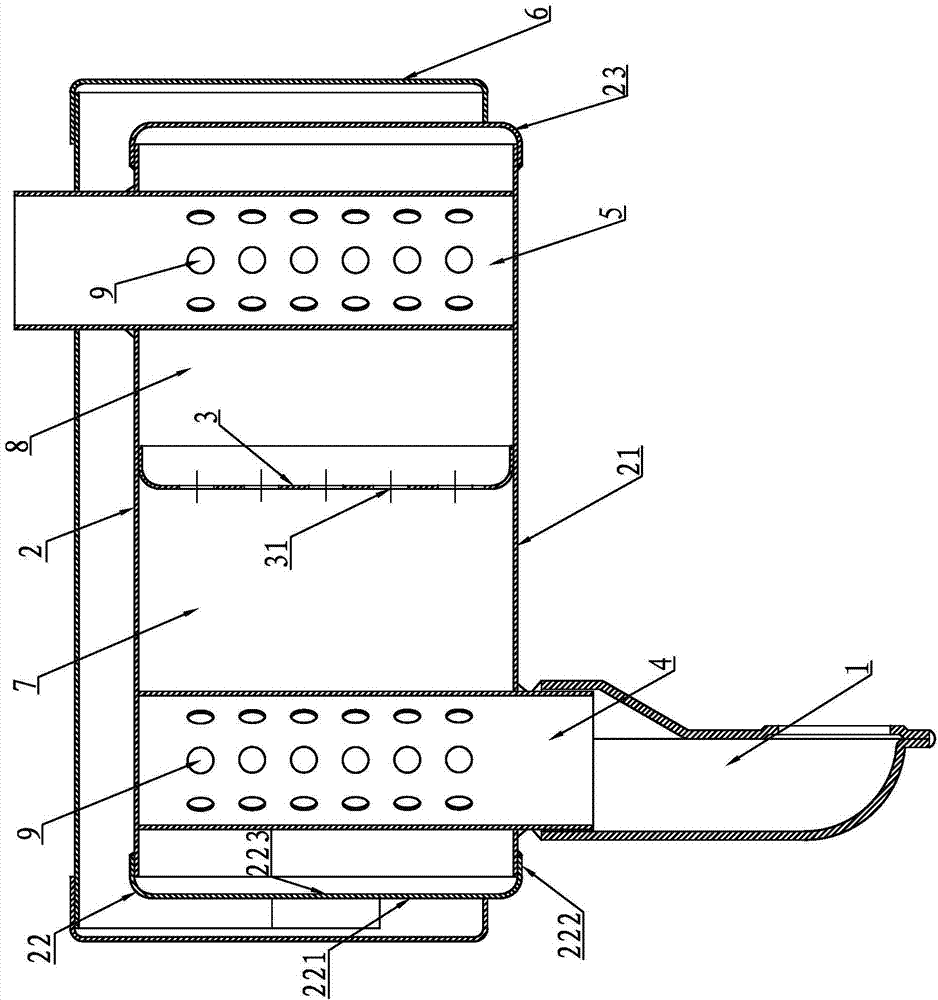
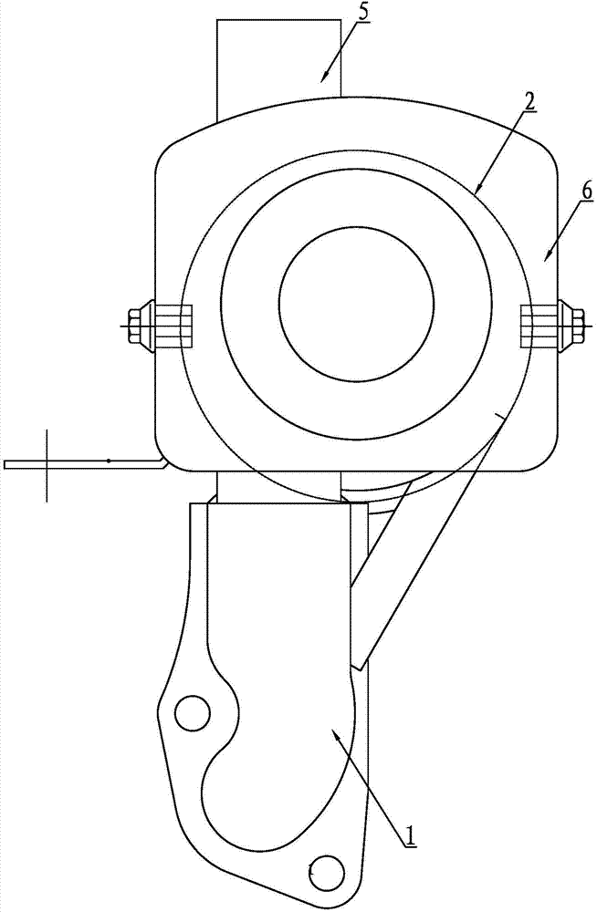
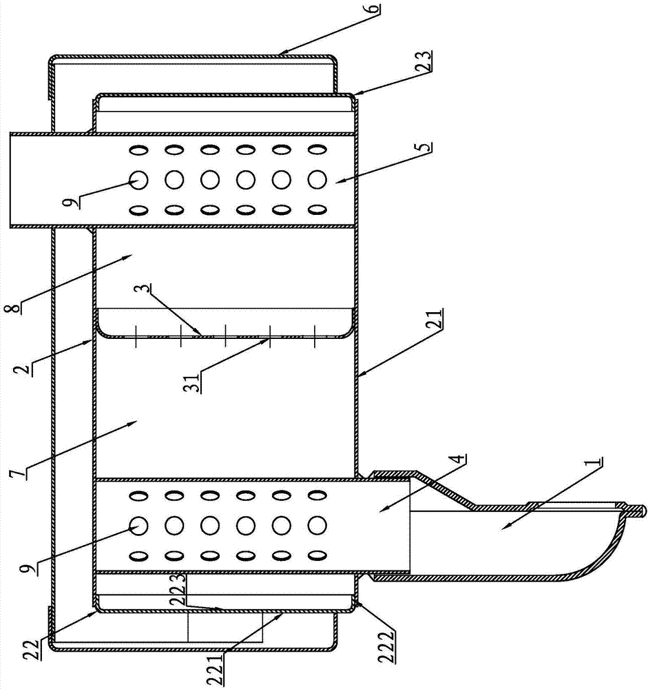
[0024] A diesel engine muffler with cavity anechoic chamber structure, such as Figure 1~2 As shown, it includes the intake pipe 1, the non-stretching sound-absorbing shell 2, the sound-absorbing partition 3, the primary noise-reducing pipe 4, the terminal noise-reducing pipe 5 and the anti-scalding shield 6, and the stretch-free sound-absorbing shell 2 is composed of a profile pipe body 21. The left end cap 22 and the right end cap 23 are composed, the profile pipe body 21 is a round pipe, the left end cap 22 and the right end cap 23 are cup cap structures, and the left end cap 22 consists of an end face 221, a matching journal 222 and a pit 223, the end face 221 and the matching journal 222 enclose a recess 223, the inner surface of the matching journal 222 matches the outer surface of the profile pipe body 21, and is welded together in a sealed manner. The structure of the right end cover 23 is the same as that of the left end cover 22. The structure is the same, and the ma...
Embodiment 2
[0026] Compared with the above-mentioned embodiment 1, the difference is that the left end cap 22 and the right end cap 23 are connected with the profile pipe body 21 in a different way, and the left end cap 22 is matched with the outer surface of the journal 222 and the inner surface of the profile pipe body 21. Cooperate and seal welded into one, the matching connection mode of the right end cover 23 and the profile pipe body 21 is all the same as the structure of the left end cover 22, as image 3 shown.
Embodiment 3
[0028] The difference from Embodiment 1 is that the left end cap 22 and the right end cap 23, in this example, the left end cap 22 and the right end cap 23 are plate-type circular end caps, such as Figure 4 shown.
[0029] There are many embodiments of the present invention, and the applicant cannot list them repeatedly. For example, the sound-absorbing partition 3 can be vertically arranged in the profile pipe body 21, or it can be as follows: Figure 5As shown in the horizontal setting, the profile pipe body 21 can be a circular pipe or a rectangular pipe. The shape of the sound-absorbing partition 3 and the aperture size of the sound-absorbing holes 31 on it can also be changed. All the sound-absorbing holes 31 on the sound-absorbing partition 3 The ratio of the sum of the areas and the volume of the primary noise reduction cavity 7 can be changed accordingly. All technical solutions as long as the profile pipe body 21 is used as the sound-absorbing shell are within the s...
PUM
 Abstract
Description
Claims
Application Information
 - R&D
- Intellectual Property
- Life Sciences
- Materials
- Tech Scout
- Unparalleled Data Quality
- Higher Quality Content
- 60% Fewer Hallucinations
Browse by: Latest US Patents, China's latest patents, Technical Efficacy Thesaurus, Application Domain, Technology Topic, Popular Technical Reports.
© 2025 PatSnap. All rights reserved.Legal|Privacy policy|Modern Slavery Act Transparency Statement|Sitemap|About US| Contact US: help@patsnap.com


