Gesture recovery and recognition method based on time domain Doppler effect

A recognition method and gesture technology, applied in the reflection/re-radiation of radio waves, measuring devices, instruments, etc., can solve the problems of simple application of limited gesture games and huge hardware cost, and achieve high sensitivity, low hardware complexity, The effect of strong robustness

Inactive Publication Date: 2014-05-14
ZHEJIANG UNIV
7 Cites 24 Cited by

AI-Extracted Technical Summary

Problems solved by technology

[0004] Traditional gesture recovery recognition uses computer image processing technology, which consumes huge hardware costs and require...

Abstract

The invention discloses a gesture recovery and recognition method based on the time domain Doppler effect. A one-way transmitter is adopted for transmitting a single-frequency signal through an antenna; because of the Doppler effect, gesture motion information is modulated into the phase position of a reflected signal; receiving antennae of a plurality of receivers are placed in the best signal receiving positions, the multiple receivers and the transmitter share a same reference clock, phase synchronization is guaranteed, a radio frequency reflection signal is down-converted into medium frequency by a medium frequency receiver module, the medium frequency signal is down-converted into a digital baseband signal in an orthogonal mode by a digital down-conversion module, the digital baseband signal is collected by a signal collection module of a computer, the signal is processed through a comprehensive algorithm of time domain demodulation, and then gesture recovery and recognition based on the time domain Doppler effect is carried out. The method is high in sensitivity and robustness and low in hardware complexity; the accurate two-dimensional and three-dimensional motion information of gestures can be accurately recovered; any motion of a hand can be detected with the method, and the method will be widely applied to the field of gesture recognition based on the Doppler effect.

Application Domain

Technology Topic

Radio frequencyThree dimensional motion +12

Image

  • Gesture recovery and recognition method based on time domain Doppler effect
  • Gesture recovery and recognition method based on time domain Doppler effect
  • Gesture recovery and recognition method based on time domain Doppler effect

Examples

  • Experimental program(1)

Example Embodiment

[0023] Below in conjunction with accompanying drawing, specifically set forth the working principle and the implementation mode of the present invention:
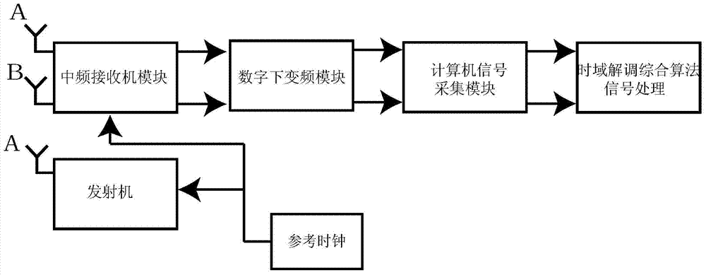
[0024] like figure 1 As shown, the present invention uses a single-channel transmitter to transmit a single-frequency signal through an antenna. Due to the Doppler effect, the gesture motion information is modulated into the phase of the reflected signal; the receiving antennas of multiple receivers are placed in the best signal receiving position , Multiple receivers and transmitters share the same reference clock to ensure phase synchronization. The IF receiver module down-converts the RF reflection signal to IF, and the digital down-conversion module quadrature down-converts the IF signal to a digital baseband signal. Computer signal acquisition The module collects digital baseband signals, uses time-domain demodulation comprehensive algorithm signal processing, and performs time-domain Doppler gesture recovery recognition.
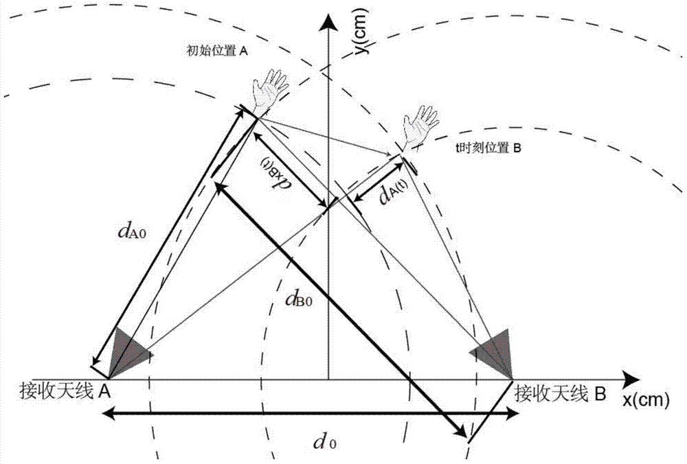
[0025] like figure 2 As shown, for the two-dimensional case, two receivers are needed, which is equivalent to taking the receiving antennas A and B of the two receivers as the centers at each moment, and using the arctangent or enhanced differential cross multiplication algorithm to convert the digital baseband signal Demodulate the distance to the receiving antenna of the receiver, draw a circle with this distance as the radius, and the intersection point of the circle constructed by the two signals at the same time is the position of the gesture at this moment, and the track of the intersection point changing with time is Accurate trajectory of gesture movements.
[0026] For the two-dimensional case, at least two receivers are required, and the distances between the initial position of the gesture movement and the receiving antennas A and B of the receiver are known, respectively d A0 、d B0 , the distance change value of the gesture movement relative to the receiving antenna A and B of the receiver at time t is d A (t), d B (t), using the arctangent or enhanced differential cross multiplication algorithm to demodulate the digital baseband signal to obtain the distance d relative to the receiving antenna of the receiver A0 +d A (t), d B0 +d B (t), at time t, take the receiving antennas A and B of the two receivers as the center of the circle respectively, and take the receiving antenna distance d of the corresponding receiver A0 +d A (t), d B0 +d B (t) Draw a circle for the radius, and the intersection point of the circle constructed by the two signals at the same time is the position of the gesture at this time. The trajectory of the intersection point changing with time is the accurate trajectory of the gesture movement.
[0027] For the three-dimensional case, three-way receivers are required, and the receiving antennas of the three-way receivers are not on the same plane. The trajectory of the ball intersection constructed after signal demodulation is the precise trajectory of gesture movement.
[0028] For the three-dimensional situation, at least three receivers C, D, and E are required, and the receiving antennas of the three receivers are not in the same plane, and the distance between the initial position of the gesture movement and the receiving antenna of the receiver is known, respectively d C0 、d D0 , d E0 , the distance change value of the gesture movement relative to the receiving antenna C, D, E of the receiver at time t is d C (t), d D (t), d E (t), using arctangent or enhanced differential cross multiplication algorithm to demodulate the digital baseband signal to obtain the distance d of the receiving antenna relative to the receiver C0 +d C (t), d D0 +d D (t), d E0 +d E (t), at time t, take the receiving antennas C, D, and E of the three receivers as the center of the circle respectively, and take the receiving antenna distance d of the corresponding receiver as C0 +d C (t), d D0 +d D (t), d E0 +d E (t) draws a ball with a radius, the intersection point of the ball constructed by the two signals at the same time is the position of the gesture at this moment, and the trajectory of the constructed ball intersection is the precise trajectory of the gesture movement.
[0029] like image 3 , Figure 4 Shown is the locus diagram of the construction circle intersection of the motion information of the two-dimensional object.
[0030] Assume that the single-frequency transmit signal expression is:
[0031]
[0032] S(t) is the transmitting signal, t is the time, f is the transmitting frequency, is the transmitter phase noise.
[0033] then pass figure 1 The signals received by the receiving antennas A and B of the receiver are respectively
[0034] R A = cos ( 2 πft - 4 π d A 0 λ - 4 πd A ( t ) λ ) ,
[0035] R B = cos ( 2 πft - 2 πd A 0 λ - 2 π d B 0 λ - 2 πd A ( t ) λ - 2 πd B ( t ) λ )
[0036] Among them, R A , R B are the signals received by the receiving antennas A and B of the receiver respectively, f is the transmitting frequency, d A0 and d B0 is the initial position of receiving antennas A and B from the human hand to the receiver, d A (t) and d B (t) are respectively the change value of the distance between the gesture movement and the receiving antenna A and B of the receiver at time t.
[0037] use figure 1 As shown, the motion distance change information d relative to the receiving antenna direction of the receiver is extracted A (t) and d B (t), taking the receiving antennas A and B of the receiver as the center respectively, d A +d A (t) and d B +d B (t) Draw a circle with radius. like image 3 , Figure 4 , it can be seen that the trajectory of the intersection of the two circles over time at the same moment is the exact trajectory of the gesture movement.
[0038] like Figure 5 , Image 6 As shown, the change of the moving distance of the two-dimensional uniform gesture movement relative to the receiving antennas of the two receivers is the distance change of the receiving antennas along the wave vector direction of the received electromagnetic wave. Therefore, the distance variation diagram of the receiving antennas relative to the two receivers is d A +d A (t) and d B +d B(t) Plot over time. The simulation increases the impact of white noise on the gesture recovery results to test the robustness of the present invention, as Figure 5 is the distance change diagram for the receiving antenna A, such as Image 6 It is the distance change diagram for the receiving antenna B.
[0039] like Figure 7 (normalized coordinates), Figure 7 for Figure 5 , Image 6 For the two-dimensional uniform-velocity gesture movement, the gesture recovery trajectory obtained by using the time-domain demodulation synthesis algorithm can be seen that the gesture movement can be accurately recovered. Figure 8 Gesture recovery trajectories obtained for sinusoidal motion recovery.

PUM

no PUM

Description & Claims & Application Information

We can also present the details of the Description, Claims and Application information to help users get a comprehensive understanding of the technical details of the patent, such as background art, summary of invention, brief description of drawings, description of embodiments, and other original content. On the other hand, users can also determine the specific scope of protection of the technology through the list of claims; as well as understand the changes in the life cycle of the technology with the presentation of the patent timeline. Login to view more.

Similar technology patents

Integrated microfluidic optical device for sub-micro liter liquid sample microspectroscopy

InactiveUS20090051901A1Great sensitivityHigh sensitivityRadiation pyrometrySpectrum investigationSpectroscopySpectroscopic detection
Owner:DYNAMIC THROUGHPUT

Classification and recommendation of technical efficacy words

  • High sensitivity
  • Reduce hardware complexity

System and method for optical coherence imaging

ActiveUS20060055936A1Sufficient signal to noise ratioHigh sensitivityInterferometersScattering properties measurementsPhysicsCoherent imaging
Owner:THE GENERAL HOSPITAL CORP

Catheter-free implantable needle biosensor

ActiveUS20080033269A1High sensitivitySimple stepSurgeryVaccination/ovulation diagnosticsNeedle electrodeElectricity
Owner:VIRTUE MEDICAL TECH (HUZHOU) CO LTD

Antenna selection method based on full cross weight genetic algorithm

InactiveCN102208934AIncrease channel capacityReduce hardware complexitySpatial transmit diversityWeight valueChannel capacity
Owner:BEIJING INSTITUTE OF TECHNOLOGYGY

Staggered type power factor correction circuit and control method thereof

ActiveCN104038042AReduce measurement errorReduce hardware complexityEfficient power electronics conversionPower conversion systemsPower factor correction circuitsDuty cycle
Owner:GREE ELECTRIC APPLIANCES INC OF ZHUHAI

Character defect detection method and device based on morphology

ActiveCN109142383AReduction of Mechanical Datum Accuracy RequirementsReduce hardware complexityOptically investigating flaws/contaminationLight sourceDigitization
Owner:郭江波
Why Eureka
Try Eureka