LED drive device, battery charger and drive control circuit of LED drive device

A technology for driving control circuits and control modules, which is applied in the direction of electric lamp circuit layout, lighting devices, emergency protection circuit devices, etc., and can solve problems affecting the service life of constant current drive sources, so as to improve safety and reliability, and use flexibility High and wide application effect

Inactive Publication Date: 2014-05-14
陈俞好
View PDF12 Cites 6 Cited by
  • Summary
  • Abstract
  • Description
  • Claims
  • Application Information

AI Technical Summary

Problems solved by technology

[0004] The technical problem to be solved by the present invention is to provide a drive for the existing technology that most of the circuits that convert the power supply into a constant current or constant voltage drive source contain electrolytic capacitors, which affect the service life of the constant current drive source. Control circuit, simple circuit and long service life
[0005] Another technical problem to be solved by the present invention is to provide an A kind of LED driving device, wherein the driving control circuit connection structure is simple and the service life is long
[0006] Another technical problem to be solved by the present invention is to provide an A battery charger in which the drive control circuit has a simple connection structure and a long service life

Method used


Image

  • LED drive device, battery charger and drive control circuit of LED drive device
  • LED drive device, battery charger and drive control circuit of LED drive device
  • LED drive device, battery charger and drive control circuit of LED drive device

Examples


Embodiment Construction

[0026] In order to allow those skilled in the art to better understand the technical solutions of the present invention, the present invention will be further described below in conjunction with the accompanying drawings.

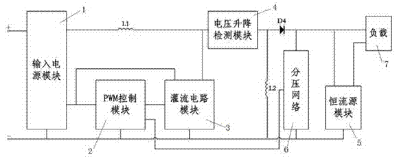
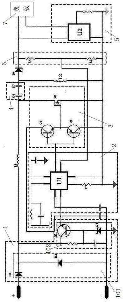
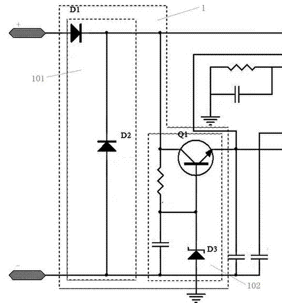
[0027] The specific embodiment of the present invention is as Figure 1 ~ Figure 2 As shown, a drive control circuit includes an input power supply module 1 connected to the input terminal, a PWM control module 2 connected to the input power supply module, and is characterized in that it also includes a perfusion circuit connected to the output terminal of the PWM control module 2 The circuit module 3, the voltage rise and fall detection module 4 connected to the input power supply module 1 through the inductance L1 which acts as a blocking filter, and the constant current source module 5 connected to the voltage rise and fall detection module 4 through a diode D4, wherein the perfusion circuit module The working power of 3 is provided by the output end of ...


PUM


Abstract

The invention relates to a drive control circuit which comprises an input power module connected with an input end, a PWM control module connected with the input power module, a perfusion circuit module connected with the output end of the PWM control module, a voltage fluctuation detection module connected with the input power module through an inductor L1 and a constant current source module connected with the voltage fluctuation detection module through a diode D4, wherein the constant current source module is connected with a load. Compared with the prior art, the drive control circuit has the advantages that an electrolysis capacitor is not included in the circuit, the circuit is simple in structure and can be conveniently integrated and miniaturized, and the service life of a power supply is long; the input power module has a reverse-connection-proof function, when the power supply is reversely connected, the circuit does not work, and safety and reliability of the circuit are effectively improved; output wide voltages and currents are adjustable, the adjustable interval is large, use flexibility is high, the application range is wide, and popularization is easy to achieve; the voltage fluctuation detection module can meet requirements for multiple functions and variety.

Description

technical field [0001] The invention relates to the technical field of load drive circuit control, in particular to a drive control circuit that provides constant voltage and constant current for loads. Background technique [0002] The use of LED lamps to realize lighting is becoming more and more widely used, but LED lamps cannot be directly connected to the power supply, but need to use a stable power supply as its driving power to work normally. There are various driving methods for LEDs. Most of the current LED drive power supply adopts the constant current method of switching voltage regulation, but this method is costly, the circuit is more complicated, and there will be electromagnetic interference; most of the circuits that convert the power supply into a constant current drive source include electrolytic capacitors. The electrolytic capacitor electrolyte is easy to dry up and be broken down, which affects the service life of the constant current drive source. [0...

Claims


Application Information

Patent Timeline
Patent Type & Authority Applications(China)
IPC IPC(8): H05B37/02H02H11/00
Inventor 陈俞好
Owner 陈俞好
Why Eureka
Try Eureka