Heat pump device and method for controlling heat pump device
A technology of a heat pump device, a leak detection device, applied in the field of safety, capable of solving problems such as refrigerant heat exchanger or piping leakage, fire, etc.
- Summary
- Abstract
- Description
- Claims
- Application Information
AI Technical Summary
Problems solved by technology
Method used
Image


Examples
Embodiment approach 1
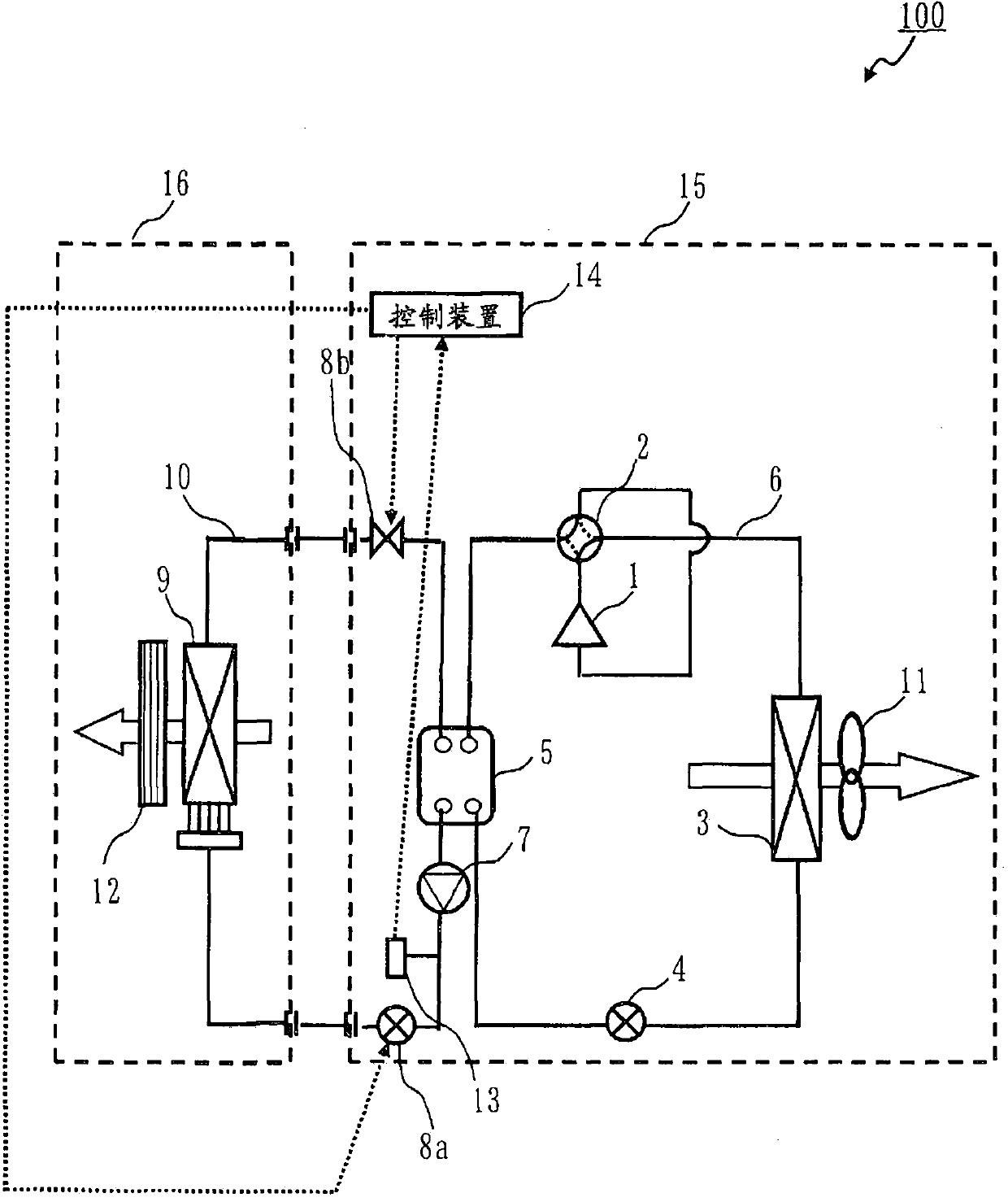
[0033] figure 1 It is a block diagram of the air conditioner 100 of Embodiment 1. in addition, figure 1 In , the blank arrow indicates the flow direction of the wind, and the dotted arrow indicates the flow direction of the signal.
[0034] The air conditioner 100 has a refrigerant circuit 6 (first refrigerant circuit, primary side circuit), and the refrigerant circuit 6 is sequentially connected to a compressor 1 (first compressor), a four-way valve 2 , and a heat exchanger 3 (a first refrigerant circuit) via pipes. 1 heat exchanger), the expansion valve 4 (first expansion mechanism), and the intermediate heat exchanger 5 (first intermediate heat exchanger) are formed in an annular shape. In addition, the air conditioner 100 has a water circuit 10 (fluid circuit, secondary side circuit), and the water circuit 10 is sequentially connected to the intermediate heat exchanger 5, the pump 7, the valve 8a (first valve), and the heat exchanger 9 (load exchanger) through piping. H...
Embodiment approach 2
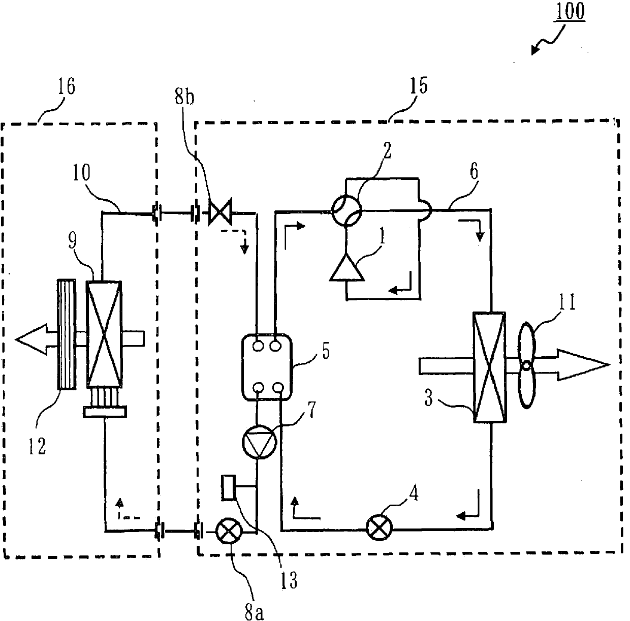
[0068] In Embodiment 2, the air conditioner 100 provided with several primary side circuits is demonstrated. In addition, although the air conditioner 100 which has two primary side circuits was demonstrated as an example here, the air conditioner 100 may have three or more primary side circuits.
[0069] Regarding the air conditioner 100 according to Embodiment 2, the same components as those of the air conditioner 100 according to Embodiment 1 are denoted by the same reference numerals.
[0070] Figure 5 It is a block diagram of the air conditioner 100 of Embodiment 2. In addition, in figure 1 In , the blank arrows indicate the direction of wind flow, and the dashed arrows indicate the direction of signal flow.
[0071] The air conditioner 100 has a refrigerant circuit 6a (first refrigerant circuit, primary side circuit), and the refrigerant circuit 6a is sequentially connected to a compressor 1a (first compressor), a four-way valve 2a, and a heat exchanger 3a (a first r...
Embodiment approach 3
[0105] In Embodiment 3, the arrangement of the intermediate heat exchangers 5 ( 5 a , 5 b ) in Embodiments 1 and 2 will be described. In addition, the air conditioner 100 of Embodiment 2 is demonstrated here as an example.
[0106] Figure 8 It is an exploded perspective view of a general plate heat exchanger.
[0107] Figure 9 to Figure 11 It is a figure which shows the arrangement|positioning of the intermediate heat exchanger 5a, 5b of Embodiment 3. exist Figure 9 to Figure 11In , solid arrows indicate the flow of refrigerant during the cooling operation, and dotted arrows indicate the flow of water. During the heating operation, the refrigerant flows in the direction opposite to that of the solid arrow. and, in Figure 9 to Figure 11 In , the up-down direction represents the vertical direction.
[0108] exist Figure 9 to Figure 11 In , it is assumed that the intermediate heat exchangers 5a, 5b are plate heat exchangers. Such as Figure 8 As shown, the plate he...
PUM
 Abstract
Description
Claims
Application Information
 - R&D
- Intellectual Property
- Life Sciences
- Materials
- Tech Scout
- Unparalleled Data Quality
- Higher Quality Content
- 60% Fewer Hallucinations
Browse by: Latest US Patents, China's latest patents, Technical Efficacy Thesaurus, Application Domain, Technology Topic, Popular Technical Reports.
© 2025 PatSnap. All rights reserved.Legal|Privacy policy|Modern Slavery Act Transparency Statement|Sitemap|About US| Contact US: help@patsnap.com