Bionic zoom lens and driving device thereof

A zoom lens and driving device technology, applied in the field of bionic machine vision, can solve the problems of complex structure, limited response speed, poor optical axis stability, etc., and achieve the effect of good imaging quality, rapid response, and stable optical axis

Inactive Publication Date: 2014-05-21
ZHEJIANG UNIV
View PDF3 Cites 15 Cited by
  • Summary
  • Abstract
  • Description
  • Claims
  • Application Information

AI Technical Summary

Problems solved by technology

The zoom system is usually realized by the traditional method, that is, the optical system is composed of different concave-convex lenses, and the focal length is adjusted by adjusting the relative position of each component by moving back and forth. This method appeared earlier and the technology is more mature, but the bionic characteristics are weak and the structure is complicated. , limited response speed, large size, easy to wear
In recent years, some researchers at home and abroad have proposed liquid zoom lenses, mainly mechanically driven liquid lenses and electrowetting liquid lenses, which can realize the zoom function of the human eye to a certain extent, but they use liquid as the optical medium, which is easy to produce Leakage and poor optical axis stability make it difficult to meet practical application requirements
[0005] A bionic eye device with zoom characteristics is disclosed in the prior art (application publication number 103192412 A), which uses a solid-state zoom lens for a bionic eye, uses a linear stepper motor to control the zoom lens zoom, and imitates the ciliary muscle of the human eye to drive the lens The realization of the zoom process has the characteristics of simple structure and easy preparation. However, the zoom lens used in this technology adopts an integrated lens structure, and the plano-convex lens and the PDMS lens are simply bonded together. Due to the characteristics of zooming, and the imaging quality is difficult to guarantee, the PDMS filled in the middle of the lens has strong fluidity, which affects the stability of the optical axis of the lens. Using a stepping motor to drive the compression disc to squeeze the zoom lens to achieve zooming, the control accuracy and response speed are difficult to guarantee. , the overall size of the device cannot meet the miniaturization requirements

Method used


Image

  • Bionic zoom lens and driving device thereof
  • Bionic zoom lens and driving device thereof
  • Bionic zoom lens and driving device thereof

Examples


Embodiment Construction

[0025] The following will clearly and completely describe the technical solutions in the embodiments of the present invention with reference to the accompanying drawings in the embodiments of the present invention. Obviously, the embodiments described below are some, not all, embodiments of the present invention. Based on the embodiments of the present invention, all other embodiments obtained by persons of ordinary skill in the art without making creative efforts belong to the protection scope of the present invention.

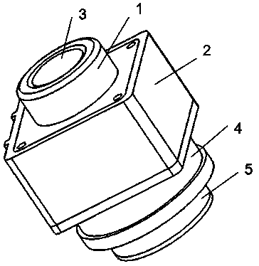
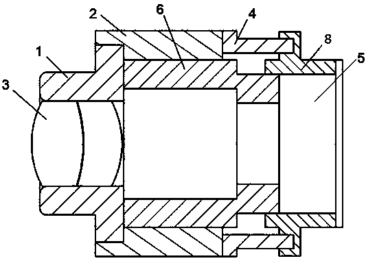
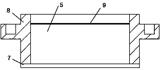
[0026] Such as Figure 4 As shown, a bionic zoom lens includes a double cemented dioptric objective lens 3 at the front end and a colloid lens 5 at the rear end; the double cemented dioptric objective lens 3 is used as the first lens unit of the zoom lens to pre-refract the light, It is made of a low-dispersion double-convex positive lens and a highly-dispersive concave-convex negative lens, and its diopter is 40D; the colloid lens 5 is used as the second len...


PUM


Abstract

The invention discloses a bionic zoom lens and a driving device thereof. A double gluing refraction object lens and a colloid lens are used as refraction devices. Light rays are refracted in advance by simulating zooming characters of a cornea and a crystalline lens of a human eye and using the double gluing refraction object lens as a first lens unit of the zoom lens, and the colloid lens is used as a second lens unit, and accordingly the crystalline lens of the human eye is simulated. Continuous zooming in a zooming range required in design is achieved by respectively installing an object lens fixing frame and a fixing sleeve at two ends of a voice coil motor, installing the double gluing refraction object lens in the object lens fixing frame, connecting a press ring and an inner ring of the voice coil motor together through a thread, enabling the rear end face of the press ring to contact with the front surface of the colloid lens, connecting the fixing sleeve and a housing of the colloid lens together, and using the inner ring of the voice coil motor to drive the press ring to squeeze the front surface of the colloid lens so as to change surface curvature of the colloid lens. The bionic zoom lens and the driving device thereof have the advantages of being stable in optical axis, good in imaging quality, rapid in response and the like, and can be widely used in robot vision systems and a variety of modern imaging systems.

Description

technical field [0001] The invention relates to bionic machine vision, in particular to a bionic zoom lens based on a colloid lens and a driving device thereof. Background technique [0002] With the continuous development and progress of the level of science and technology, people's demand for intelligent and automated products is increasing day by day, and these have become the focus of research in the field of engineering science. Robot is a robot with a high degree of automation. It integrates many high technologies and has been researched and applied in the fields of industry, military, anti-riot, medical treatment, and service. For robots, the visual system is an important way to obtain external information, and it occupies a particularly important position in the research of intelligent robots. With the development of industrial technology and intelligent technology, the development of machine vision system has made great progress, but it still lags behind the visual...

Claims


Application Information

Patent Timeline
Patent Type & Authority Applications(China)
IPC IPC(8): G02B3/00G02B1/04G02B7/04
Inventor 王宣银梁丹向可曹松晓杜佳玮杨俊男
Owner ZHEJIANG UNIV
Why Eureka
Try Eureka