Stator permanent magnet mixed stepping motor

A technology of stepping motors and permanent magnets, applied in the direction of electromechanical devices, electrical components, magnetic circuit rotating parts, etc., can solve the uneven distribution of air gap permanent magnet flux density along the axial direction, increase the amount of permanent magnets, and increase the torque Problems such as low density and efficiency power level, to achieve uniform distribution of air-gap permanent magnet flux density, reduce processing and manufacturing difficulty, and simplify analysis and design

Inactive Publication Date: 2014-05-21
SHANDONG UNIV
View PDF6 Cites 8 Cited by
  • Summary
  • Abstract
  • Description
  • Claims
  • Application Information

AI Technical Summary

Problems solved by technology

[0007] 1. Since the permanent magnet is placed on the rotor and placed in the middle of the two-stage laminated rotor core, and the small teeth on the two-stage rotor must be staggered by 1 / 2 pitch from each other, the structure of the motor is complex and difficult to manufacture
[0008] 2. The permanent magnet is magnetized along the axial direction. The magnetic field generated by the permanent magnet must pass through the two rotor cores and the stator core vertically along the axial direction to form a closed circuit. Since the stator and rotor cores are composed of laminated silicon steel sheets, adjacent silicon steel sheets There is a non-magnetic insulating layer (equivalent to an air gap) between the sheets, and a large part of the magnetomotive force generated by the permanent magnet is consumed in the air gap between the core sheets, resulting in a low utilization rate of the permanent magnet, or in other words, it cannot meet the The air gap permanent magnet flux density between the stator and rotor of the motor must increase the thickness of the permanent magnet, thereby increasing the amount of permanent magnets and increasing the manufacturing cost of the motor
[0009] 3. The longer the motor stator core and the two-stage rotor core are in the axial direction, the greater the magnetomotive force consumed by the permanent magnet in the axial magnetization magnetic circuit, so the axial length of the traditional hybrid excitation stepping motor is limited. As a result, the power level of the traditional hybrid stepping motor is limited, that is, the power level of the traditional hybrid stepping motor is about 1kW at most, and it is generally used in the power level range of several W and tens of W.
[0010] 4. There is no electromechanical energy conversion within the axial length of the permanent magnet of the motor, so the power density and torque density of this type of motor are reduced. At the same time, the stator winding conductor within the axial length of the permanent magnet is just like the end of the winding. It acts as a connection and does not participate in energy conversion, which leads to a reduction in the efficiency of the motor
The lower power density, torque density and efficiency of traditional hybrid stepper motors are also important reasons for the lower power levels of this type of motor
[0011] 5. The permanent magnet magnetic field is closed along the axial direction of the stator and rotor core, resulting in uneven air-gap permanent magnet flux density in the axial direction. The air-gap permanent magnet flux density near both ends is low. The closer to the permanent magnet, the air-gap permanent magnet The higher the magnetic density, obviously, the longer the axial direction of the rotor core at both ends, the more uneven the distribution of the air gap permanent magnetic flux density along the axial direction. Since the magnetic circuit saturation degree of the stator and rotor core needs to be considered in the design of the motor, therefore This phenomenon leads to a reduction in the utilization rate of the effective materials of the motor, which leads to an increase in cost and limits the increase in the power level of the motor
[0012] 6. Due to the axial magnetization of the permanent magnet, its magnetic circuit is closed in the axial direction, and the magnetic field generated by the motor stator winding is closed in the circumferential direction, so the magnetic field of the overall motor is a standard three-dimensional field. The analysis, calculation and design of the motor bring difficulty
[0013] 7. The permanent magnet is on the rotor, and it is difficult for the permanent magnet to dissipate heat, and it is easy to cause permanent magnet demagnetization. At the same time, the reliability of the permanent magnet installed in the rotor is not easy to guarantee, especially in high-speed motors, which also limits the high speed and high power of this type of motor occasion application
[0014] As mentioned above, the traditional hybrid stepping motor, because the permanent magnet is placed on the rotor, leads to complex structure of the motor, difficulty in manufacturing, low power density and torque density, low operating efficiency, low material utilization rate, high cost, and limited The improvement of the power level of this kind of motor, although this kind of motor has the advantages of simple control system and low cost, it is at a disadvantage in the competition with other types of motors in applications with a power level greater than 1 kW. The greater the power level, the disadvantage more obvious

Method used


Image

  • Stator permanent magnet mixed stepping motor
  • Stator permanent magnet mixed stepping motor
  • Stator permanent magnet mixed stepping motor

Examples


Embodiment Construction

[0062] The present invention will be further described below in conjunction with the accompanying drawings and embodiments.

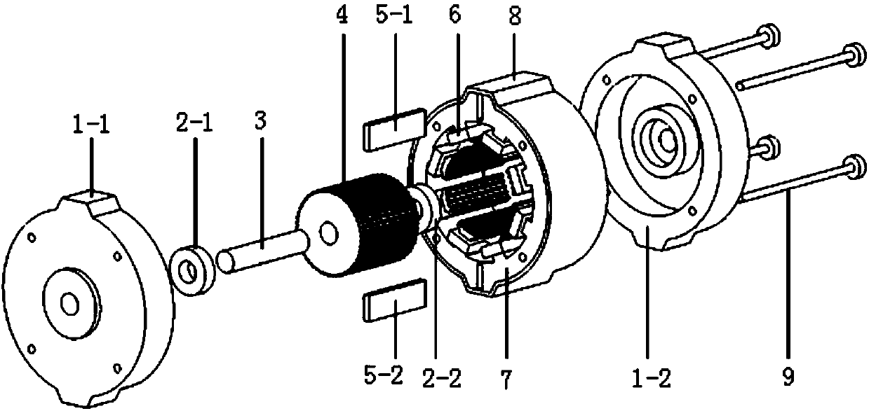
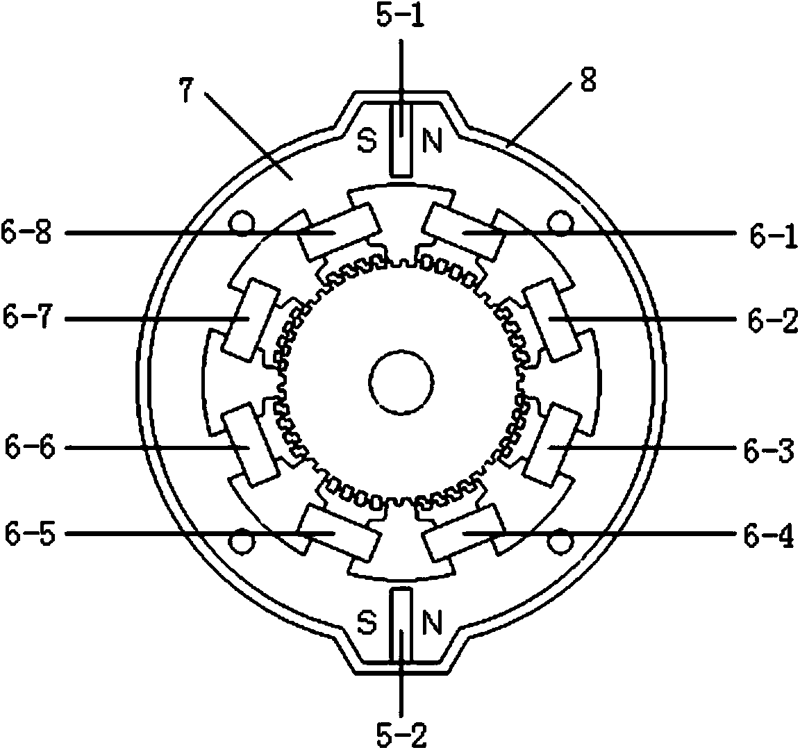
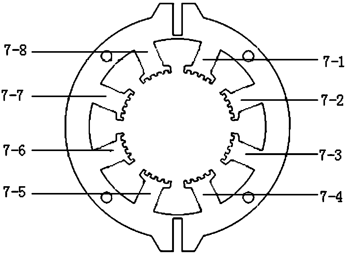
[0063] A stator permanent magnet hybrid excitation stepping motor includes a stator part and a rotor part. The rotor part includes the rotor core 4 and the rotating shaft 3 arranged inside the core. The rotor laminated core has only one section, and the same small teeth are evenly distributed on its circumference; the stator part includes the stator core 7, the stator winding 6 and the stator permanent magnet 5. The stator The same magnetic poles are distributed on the inner circumference of the iron core 7, and the stator teeth with the same pitch as the small teeth on the surface of the rotor are distributed on the pole shoes of each magnetic pole. Coils are placed on the pole body of each magnetic pole, and the coils are connected in series or parallel to form a motor. In the multi-phase winding of the stator core, permanent magnets 5 magnetized alon...


PUM


Abstract

The invention discloses a stator permanent magnet mixed stepping motor which comprises a stator portion and a rotor portion. The rotor portion comprises a rotor overlying core and a rotary shaft in the core. Same small teeth are evenly distributed on the outer periphery of the rotor overlaying core. The stator portion comprises a stator core, a stator winding and permanent magnets. Magnetic poles are distributed on the inner periphery of the stator core. Stator small teeth with tooth gaps same as those of the rotor small teeth are distributed on pole shoes of the magnetic poles, a coil is arranged on each magnetic pole body, the coils are connected in series or in parallel to form a multi-phase winding of a stator according to a certain rule, grooves are formed along the periphery evenly at the symmetrical positions of a stator core yoke portion, the permanent magnets are arranged in the grooves and distributed evenly, magnetizing is conducted in the tangential direction, and the magnetizing directions of two adjacent permanent magnets are opposite. The motor has the advantages of being simple in structure and process, low in cost and high in efficiency, power density and torque density. Meanwhile, a motor magnetic field is a two-dimensional field, and analyzing and designing are easy.

Description

technical field [0001] The invention relates to a novel hybrid stepping motor, in particular to a hybrid stepping motor in which permanent magnets are arranged on the stator of the motor. Background technique [0002] Stepper motors have become the third major type of motor besides DC motors and AC motors. Traditional motors are mainly used as electromechanical energy conversion devices, which play a key role in the electrification of human production and life. However, as human society enters the era of automation, the functions of traditional motors can no longer meet the requirements of various motion control systems such as factory automation and office automation. In order to meet these requirements, a series of new motor systems with control functions have been developed, among which the stepping motor has its own characteristics and is widely used. [0003] Stepper motors are mostly used in CNC lathes and robot systems. In modern industry, especially in the fields ...

Claims


Application Information

Patent Timeline
Patent Type & Authority Applications(China)
IPC IPC(8): H02K1/17H02K1/14H02K1/22H02K3/18H02K37/00
Inventor 徐衍亮鲁炳林
Owner SHANDONG UNIV
Why Eureka
Try Eureka