
Fin-type self-rotating anti-eccentric sucker rod

An anti-eccentric wear and self-rotation technology, applied in drill pipe, earthwork drilling, drilling equipment, etc., can solve the problems of eccentric wear of sucker rod and tubing string

Inactive Publication Date: 2014-05-28
CHINA UNIV OF PETROLEUM (EAST CHINA)
View PDF9 Cites 2 Cited by
  • Summary
  • Abstract
  • Description
  • Claims
  • Application Information

AI Technical Summary

Problems solved by technology

[0005] In order to fundamentally solve the problem of eccentric wear between the sucker rod string and the tubing string in the pumping operation of oil and gas wells and unconventional gas wells and overcome the shortcomings of the existing anti-eccentric wear technology, the purpose of the present invention is to provide a new type of Anti-eccentric wear sucker rod, that is, to develop a fin-type self-rotating anti-eccentric wear sucker rod suitable for oil and gas wells and unconventional gas wells to prevent rod and tube wear

Method used


Image

  • Fin-type self-rotating anti-eccentric sucker rod
  • Fin-type self-rotating anti-eccentric sucker rod
  • Fin-type self-rotating anti-eccentric sucker rod

Examples


Embodiment Construction

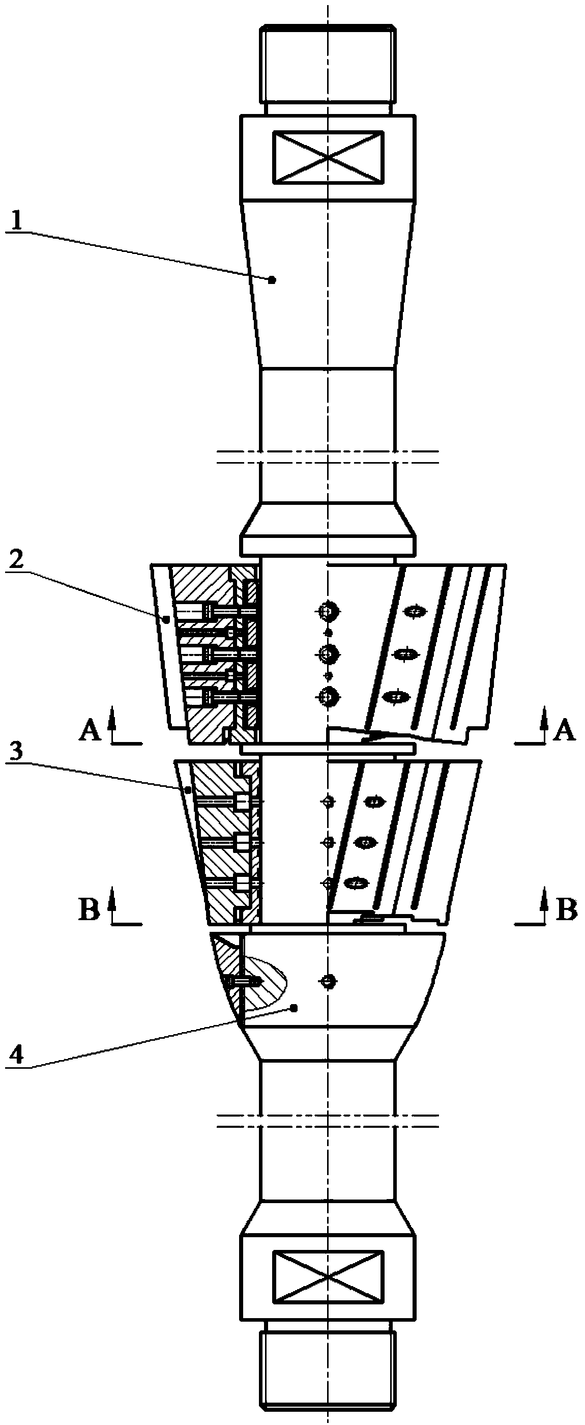
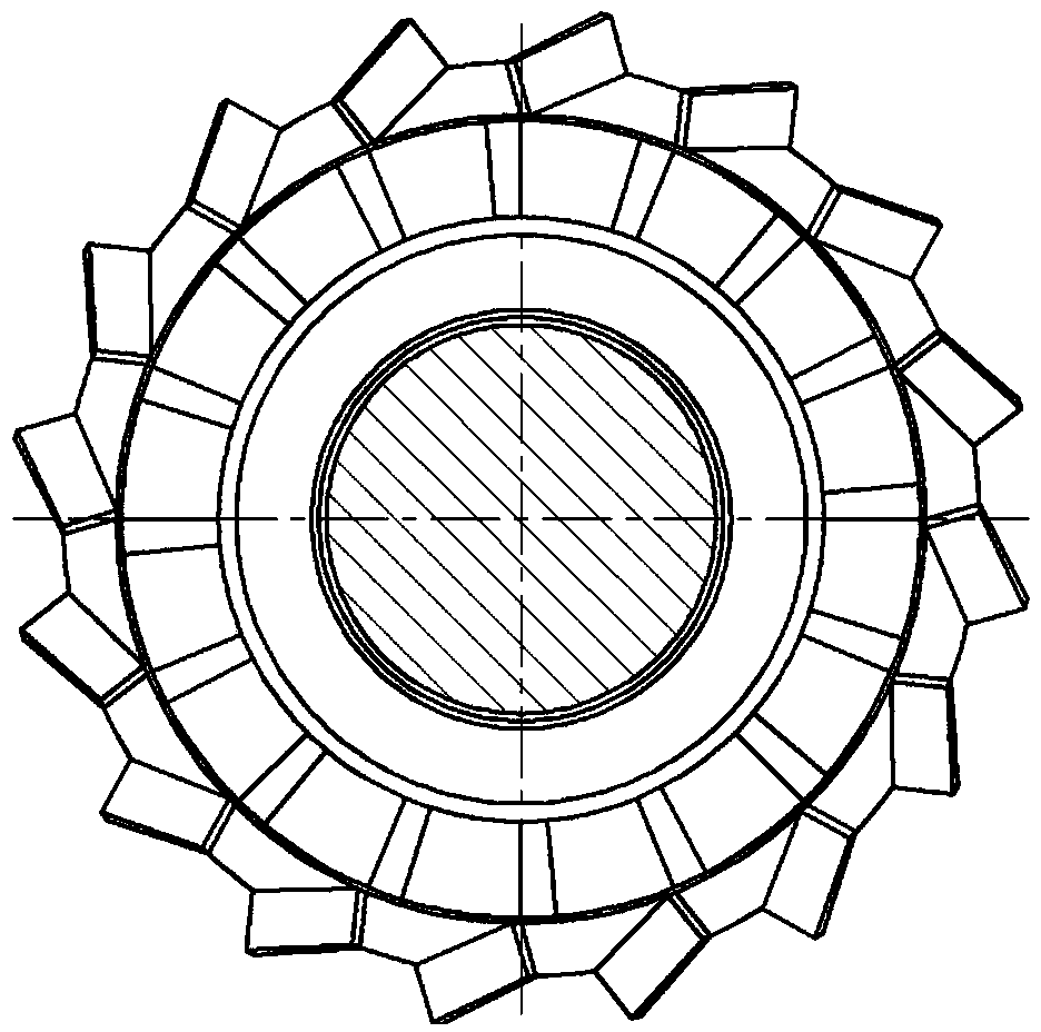
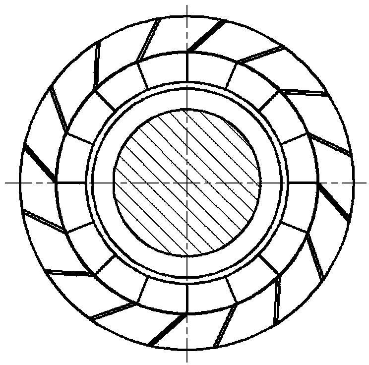
[0034] exist Figure 1 ~ Figure 3 Among them, in the three-body-one-rod structure of the fin type self-rotating anti-eccentric wear sucker rod, the three bodies refer to the turbine body 2, the thrust body 3 and the rectifier body 4, and one rod is the base rod 1, and the middle part of the base rod 1 is composed of It runs through the rectifier body 4, the thrust body 3 and the turbine body 2 sequentially from bottom to top. Before assembly, each component should be deburred and cleaned. Check in turn whether each coating and spray welding layer is firmly bonded to the base metal, whether there is any blockage in each oil guide hole, oil guide groove and oil groove, and whether the impeller teeth of the front and rear impellers exist. Collision damage, deformation, etc., whether there are defects such as bubbles, pitting, peeling and bruising on the surface of each component, etc. During assembly, the conical pipe threads and other common threads of the upper and lower threa...


PUM

PropertyMeasurementUnit
surface roughnessaaaaaaaaaa

Abstract

The invention provides a fin-type self-rotating anti-eccentric sucker rod capable of preventing abrasion to a rod and a pipe and pump clamping and prolonging the maintenance-free period of an oil and gas well. A three body and one rod structure is adopted for the first time, an oval spherical face is adopted for a rectifying body, and well liquid on the rod body can be rectified; a thrust body and the lower end step face of a turbine body form four oil wedges, and the oil wedges make friction with the well liquid to generate dynamic pressure thrust so that a fin type impeller gear can be driven to perform autorotation; converging type oil wedges are formed between the shaft body of a base rod and an oil pipe column, between the oval spherical face of the rectifying body and the oil pipe column, between the thrust body and the oil pipe column, between the conical surface of the turbine body and the oil pipe column and between a conical gear sleeve and the oil pipe column, dynamic pressure liquid films are generated, and it is guaranteed that the rod and the pipe are totally separated; the dynamic pressure liquid films on the inner layer and the outer layer of the conical gear sleeve of the turbine body form two layers of liquid films, separation between the rod and the pipe is facilitated further, and abrasion is avoided; a rod slips and a slips have the self-lubricating function, meanwhile, the liquid films generated between a slips liner and the oil wedges of the base rod can separate the turbine body and the base rod, and thus abrasion is avoided; the thrust body is rotated to stir well liquid, the flowing speed of the well liquid is increased in combination with the supercharging turbine body, and pump burying and pump blocking caused by sedimentation of sand particles can be prevented.

Description

technical field [0001] The invention relates to a downhole mechanical appliance for preventing contact and friction between a sucker rod string and a tubing string during oil and gas well suction operations, in particular to an anti-deflection device for preventing rod and tube wear, pump jamming and prolonging the repair-free period of oil and gas wells Grind the sucker rod. Background technique [0002] At present, the production of major oil and gas fields in my country has begun to enter the middle and late stage. Phenomena such as poor wellbore structure, high water content in oil, and heavy oil are very common, which makes the misalignment between the sucker rod string and the tubing string in the rod suction system The grinding problem is getting worse. In addition, the exploitation of unconventional gas wells such as coalbed methane wells has entered the stage of commercial exploitation, but the technology and experience of oil and gas recovery are still used, and th...

Claims


Application Information

Patent Timeline
Patent Type & Authority Applications(China)
IPC IPC(8): E21B17/00E21B17/10E21B19/10C23F17/00
Inventor 刘春花刘新福周超
Owner CHINA UNIV OF PETROLEUM (EAST CHINA)
Learn More