Optical fiber connector

A fiber optic connector and connector technology, applied in the coupling direction of optical waveguide, can solve the problems of low processing precision, affecting heat dissipation performance, unfavorable heat conduction, etc., and achieve the effect of reducing processing cost, improving coaxiality, and good thermal conductivity

Active Publication Date: 2014-05-28
天津凯普林光电科技有限公司
View PDF6 Cites 11 Cited by
  • Summary
  • Abstract
  • Description
  • Claims
  • Application Information

AI Technical Summary

Problems solved by technology

Due to the high difficulty and low processing accuracy of quartz glass, it is difficult to ensure the processing accuracy of the front sleeve 81 and the rear sleeve 83, especially the processing

Method used


Image

  • Optical fiber connector
  • Optical fiber connector
  • Optical fiber connector

Examples


Embodiment Construction

[0026] In order to make the object, technical solution and advantages of the present invention clearer, the implementation manner of the present invention will be further described in detail below in conjunction with the accompanying drawings. Moreover, in order to describe the positional relationship of the various structures of the present invention conveniently, the present invention defines the side close to the direction of incident light as the front side, and the opposite side as the rear side.

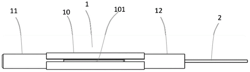
[0027] image 3 It is a schematic diagram of an optical fiber connector according to an embodiment of the present invention. The overall technical solution of the present invention is: the optical fiber connector includes a connector body 1 and a section of bare optical fiber 2 passing through the connector body 1 .

[0028] The connector body 1 includes a metal sleeve 10 , a first optical fiber fixing member 11 fixed on one end of the metal sleeve 10 , and a second optical fi...


PUM


Abstract

Disclosed in the invention is an optical fiber connector comprising a connector body and a segment of bare fiber penetrating the connector body. The connector body includes a metal sleeve, a first fiber fixed component fixed at one end of the metal sleeve, and a second fiber fixed component fixed at the other end of the metal sleeve. The bare fiber includes a first bare fiber passing through the first fiber fixed component and a second bare fiber passing through the second fiber fixed component. Because the metal sleeve and metal solder have good invasion, welding fixation of the optical fiber connector and a laser protection shell can be realized beneficially. Moreover, due to the good thermal conductivity of the metal, the heat can be transmitted to the air through the metal sleeve or be transmitted to the metal solder through the metal sleeve and then to the laser protection shell for dissipation, so that heat dissipation can be carried out beneficially.

Description

technical field [0001] The invention relates to the technical field of optical coupling devices, in particular to an optical fiber connector suitable for receiving and transmitting high-power semiconductor lasers. Background technique [0002] Generally speaking, the optical coupling of spatial light is mainly to focus or image the laser beam emitted by solid-state lasers, semiconductor lasers, etc. on the end face of the fiber core after beam shaping. The light-guiding part of the fiber is composed of the core and the cladding. , the refractive index of the core will be slightly greater than that of the cladding. In this way, when the light divergence angle incident on the end face of the fiber core is smaller than the numerical aperture NA of the fiber, it will be at the interface between the core and the cladding after entering the core. Total reflection occurs at , and when the divergence angle of light incident on the end face of the fiber core is greater than the numer...

Claims


Application Information

Patent Timeline
IPC IPC(8): G02B6/38
Inventor 杨朝栋李亚军张玉芳
Owner 天津凯普林光电科技有限公司
Why Eureka
Try Eureka