Ion beam etching depth monitoring method

A technology of ion beam etching and etching depth, which is applied in semiconductor/solid-state device testing/measurement, electrical components, circuits, etc. It can solve problems such as large differences in judgment results, difficulty in maintaining constant values, and poor stability , to achieve the effect of low price, low cost and simple experimental method

Inactive Publication Date: 2014-05-28
UNIV OF SHANGHAI FOR SCI & TECH
View PDF2 Cites 12 Cited by
  • Summary
  • Abstract
  • Description
  • Claims
  • Application Information

AI Technical Summary

Problems solved by technology

The time control method is to divide the etching depth by the etching rate of the material to be etched measured in advance to obtain the etching time of the material under the same process conditions. Since the etching rate is related to many factors, in It is difficult to maintain a constant value during the etching process, and the error is large
When using the optical path monitoring method to monitor the etching dep

Method used


Image

  • Ion beam etching depth monitoring method
  • Ion beam etching depth monitoring method
  • Ion beam etching depth monitoring method

Examples


Embodiment Construction

[0023] The method for monitoring the ion beam etching depth involved in the present invention will be further described below in conjunction with the accompanying drawings.

[0024]

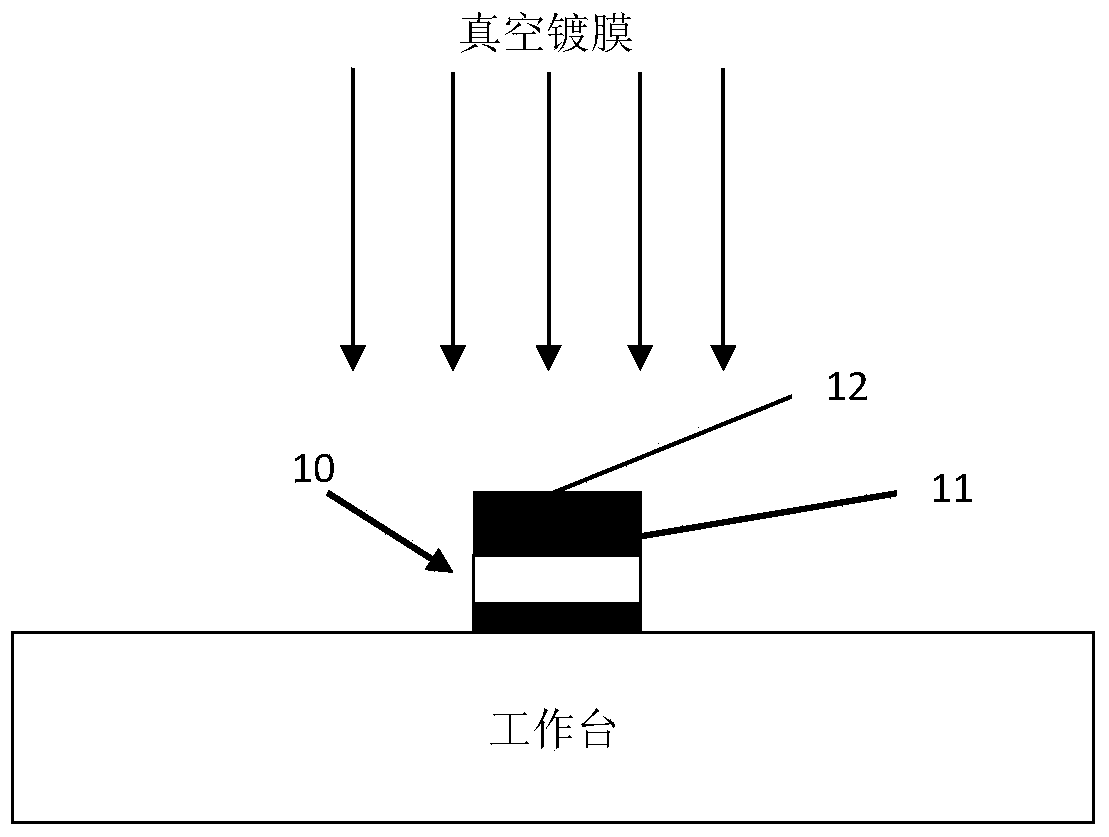
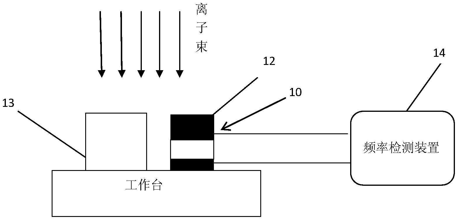
[0025] In this embodiment, energy 500ev, beam current density 1mA / cm 2 For etching under the experimental conditions of vertical incidence, the material to be etched is a silicon wafer, the standard material is an aluminum film, and the target etching depth of the silicon wafer is 190nm.

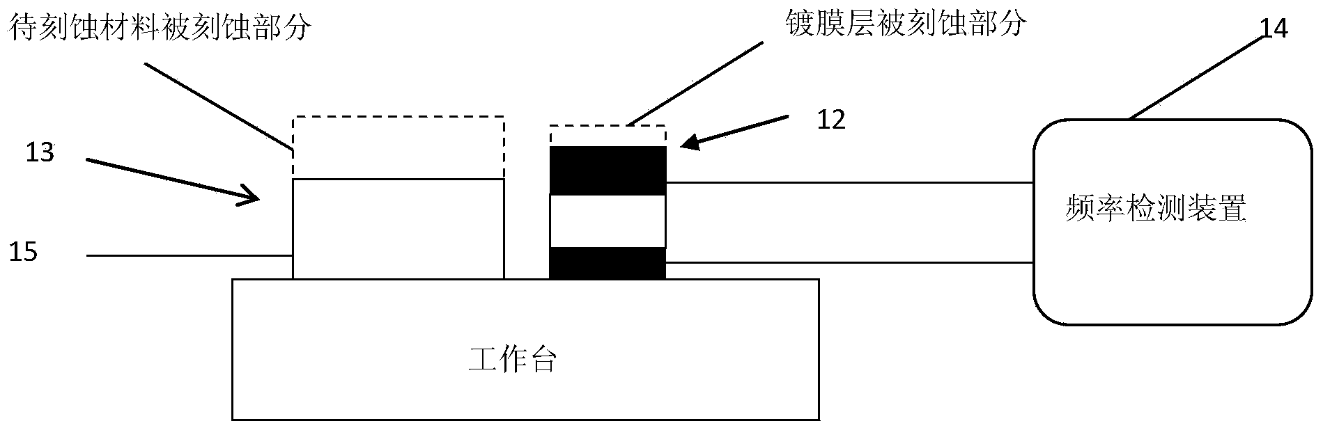
[0026] The silicon wafer and the aluminum film were respectively subjected to ion beam etching experiments under the above experimental conditions to obtain the etching rate of the aluminum film and the silicon wafer, so that the ratio of the etching rate of the aluminum film to the silicon wafer was 1.29:1.

[0027] According to the etching rate ratio of the two and the target etching depth of the silicon wafer, through calculation, the predetermined etching depth of the aluminum film is 245nm, and the prede...


PUM


Abstract

The invention provides an ion beam etching depth monitoring method. The ion beam etching depth monitoring method is characterized in that the ion beam etching depth monitoring method comprises the following steps that: step one, a layer of a standard material is plated on an electrode surface of a quartz crystal and is adopted as a plated film layer, such that a plated film quartz crystal can be obtained; step two, the plated film quartz crystal and a material to be etched are put in an ion beam etching machine, the plated film quartz crystal is connected with a frequency detection device; step three, the material to be etched and the plated film layer are etched simultaneously, and the frequency detection device monitors the etching depth of the plated film layer in real time, and when the frequency detection device monitors that the etching depth of the plated film layer achieves predetermined depth, etching is stopped, and an etched material that satisfies target etching depth can be obtained. The ion beam etching depth monitoring method provided by the invention is advantageous in simple devices, operational easiness, high precision and low cost.

Description

technical field [0001] The invention belongs to the technical field of micromachining, and in particular relates to a monitoring method for monitoring ion beam etching depth changes by using a quartz crystal oscillator method. Background technique [0002] Ion beam etching is a widely used microfabrication technology. It achieves the purpose of material removal and shaping through the physical sputtering of ion beams on materials. It has the advantages of high resolution and good orientation. [0003] Etching depth is an important indicator in ion beam etching technology, therefore, monitoring the etching depth is an important technical link in the etching process. [0004] At present, the time control method or the optical path measurement interference light intensity method are mostly used to monitor the etching depth during the etching process. The time control method is to divide the etching depth by the etching rate of the material to be etched measured in advance to o...

Claims


Application Information

Patent Timeline
IPC IPC(8): H01L21/66
CPCH01L22/12
Inventor 杨赛盛斌张大伟唐庆勇陈鹏
Owner UNIV OF SHANGHAI FOR SCI & TECH
Why Eureka
Try Eureka