Flexible battery pack and preparation method thereof

A flexible battery pack and a manufacturing method technology, which are applied in the manufacture of secondary batteries, battery pack components, and isolation of batteries from their environment, can solve the problems of decreased bonding strength, poor reliability, and great difficulty, and achieve flexibility High strength and fatigue resistance, good for flexibility, and the effect of improving bending ability

Active Publication Date: 2014-05-28
DONGGUAN AMPEREX TECH
View PDF6 Cites 26 Cited by
  • Summary
  • Abstract
  • Description
  • Claims
  • Application Information

AI Technical Summary

Problems solved by technology

However, when the flexible battery pack of this design is bent, due to the strong rigidity of the top layer and the bottom layer, the bending degree and fatigue strength of the flexible battery pack are greatly limited due to the influence of stress, which affects the performance of the flexible battery pack. After a certain bending angle and bending times, the bonding strength of the adhesive will decrease, resulting in poor reliability, and fatigue will easily occur in the non-bonding area close to the adhesive due to the inconsistent force, which is harmful to flexibility. The safety performance of the battery pack is at risk
Moreover, this method needs to control the bonding strength of the adhesive and the uniformity of the amount used in each area, and it is very difficult to mass produce

Method used


Image

  • Flexible battery pack and preparation method thereof
  • Flexible battery pack and preparation method thereof
  • Flexible battery pack and preparation method thereof

Examples


Embodiment 1

[0048] Embodiment 1 (with reference to Figure 1 to Figure 7 setting method)

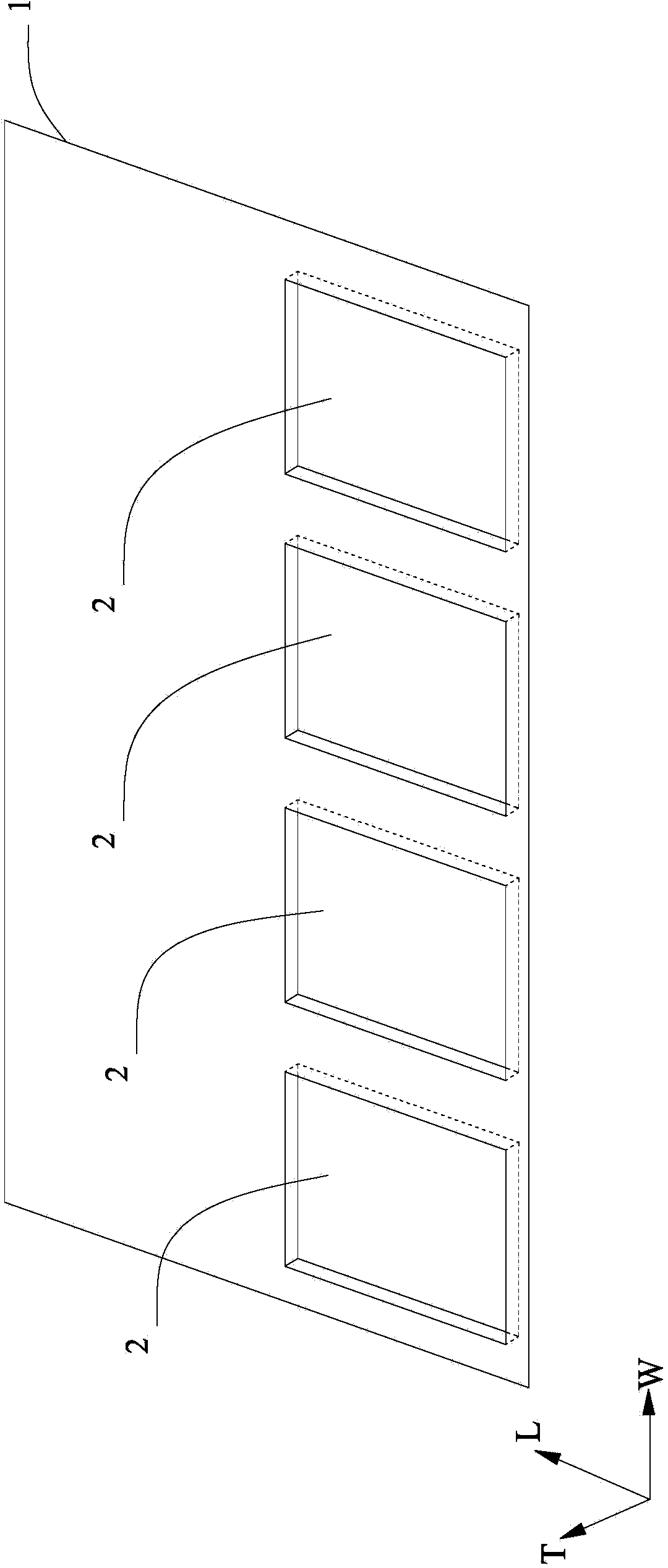
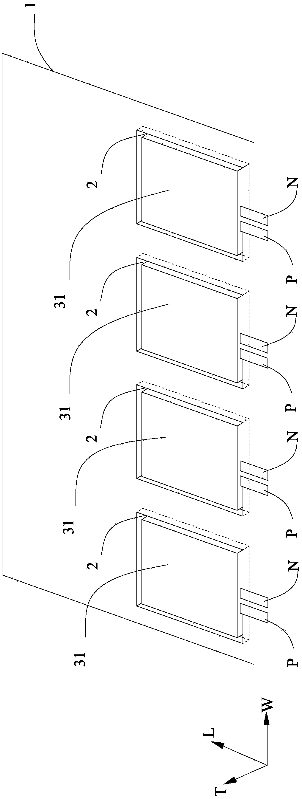
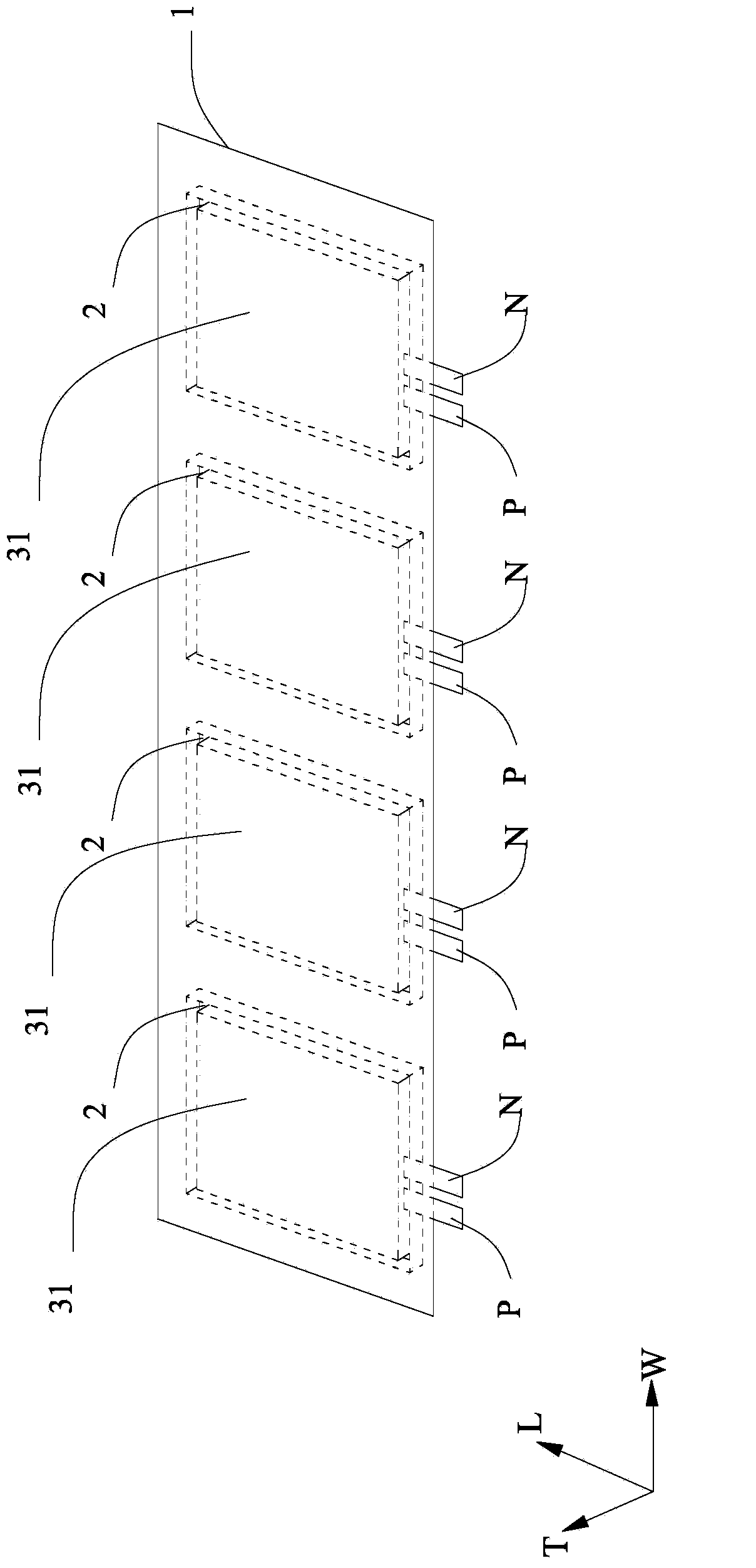
[0049] Set six punching pits 2 on the aluminum-plastic film 1, the length of the punching pits 2 is 2 mm longer than the length of the battery cell 31, the width of the punching pits 2 is 1.5 mm larger than the width of the battery cell 31, and the thickness of the punching pits 2 is larger than that of the battery cell 31. The thickness of 31 is 0.4 mm smaller; the distance between two adjacent punching pits 2 is 3 cm. Then, the battery cells 31 with a water content of 300 ppm are placed in the flushing pit 2 at intervals. Fold the other side of the aluminum-plastic film 1 in half to this side, leaving a 4cm length of the air bag G, and perform side sealing on each punching pit 2, the side sealing temperature is 195°C, the side sealing time is 20s, and the side sealing The pressure is 1MPa; top sealing is performed after injecting a liquid electrolyte containing lithium salt LiPF6 and solvent eth...

Embodiment 2

[0050] Embodiment 2 (with reference to Figure 1 to Figure 7 setting method)

[0051] Set six punching pits 2 on the aluminum-plastic film 1, the length of the punching pits 2 is 3mm longer than the length of the battery cell 31, the width of the punching pits 2 is 2.5mm larger than the width of the battery cell 31, and the thickness of the punching pits 2 is larger than that of the battery cell 31. The thickness of 31 is 0.5mm smaller; the distance between two adjacent punching pits 2 is 3.5cm. Then, the wound electric cores 31 with a water content of 250 ppm are placed into the flushing pit 2 at intervals. Fold the other side of the aluminum-plastic film 1 in half to this side, leaving a 5cm length of the air bag G, and perform side sealing on each punching pit 2, the side sealing temperature is 165°C, the side sealing time is 2s, and the side sealing The pressure is 0.2MPa; top sealing is performed after injecting a solid electrolyte containing lithium salt LiPF6, the top...

Embodiment 3

[0052] Embodiment 3 (with reference to Figure 1 to Figure 7 setting method)

[0053] Six punching pits 2 are set on the aluminum-plastic film 1, the length of the punching pits 2 is 2.5 mm longer than the length of the battery cell 31, the width of the punching pits 2 is 2 mm larger than the width of the battery cell 31, and the thickness of the punching pits 2 is larger than that of the battery core 31. The thickness of 31 is 0.45mm smaller; the distance between two adjacent punching pits 2 is 4cm. Then, the laminated battery cells 31 with a water content of 200 ppm are placed in the flushing pit 2 at intervals. Fold the other side of the aluminum-plastic film 1 to this side, leaving a length of air bag G of 4.5cm, and perform side sealing on each punching pit 2, the side sealing temperature is 180°C, the side sealing time is 10s, and the side sealing time is 10s. The sealing pressure is 0.6MPa; the top sealing is performed after injecting the gel electrolyte containing li...


PUM

PropertyMeasurementUnit
Shore hardnessaaaaaaaaaa
tensile strengthaaaaaaaaaa
lengthaaaaaaaaaa

Abstract

The invention provides a flexible battery pack and a preparation method thereof. The flexible battery pack comprises an aluminium plastic film, a plurality of batteries and a plurality of silica gels, wherein a plurality of scouring pits are arranged on the aluminium plastic film along the width direction; each battery is hermetically arranged in each scouring pit on the aluminium plastic film and is provided with a cell, a positive electrode tab, a negative electrode tab and injected electrolyte, the positive electrode tabs of the batteries are connected together, the negative electrode tabs of the batteries are connected together, and the adjacent batteries are isolated from each other; each silica gel is bonded with the aluminium plastic film parts on the sides of the scouring pits of the adjacent batteries on the two sides of the silica gel and the aluminium plastic film parts between the scouring pits of two adjacent batteries via glue. The flexible battery pack has the beneficial effects that the buckling capacity of the battery pack can be improved by adopting the silica gels, so that the safety of the batteries in the flexible battery pack can be improved; meanwhile, the silica gels are arranged outside the aluminium plastic film and the released stress is transferred from the silica gels to the aluminium plastic film when the aluminium plastic film deforms, therefore, the force finally borne by the aluminium plastic film is reduced, thus being more beneficial for the flexibility of the battery pack.

Description

technical field [0001] The invention relates to the field of batteries, in particular to a flexible battery pack and a manufacturing method thereof. Background technique [0002] Due to the many advantages of lithium-ion batteries, such as high voltage, small size, light weight, high specific capacity, no memory effect, no pollution, small self-discharge and long cycle life, etc., its application in the field of mobile devices has been unprecedented. development, including mobile phones, video cameras, notebook computers, and other portable appliances. With the development of technology for mobile and convenient devices and the increase in demand therefor, the demand for secondary batteries as energy sources is rapidly increasing. Among such secondary batteries, studies on lithium secondary batteries having high energy density and discharge voltage have been widely conducted, and are now widely used. [0003] With the interest of consumers, electronic equipment tends to be...

Claims


Application Information

Patent Timeline
Patent Type & Authority Applications(China)
IPC IPC(8): H01M2/10H01M10/04H01M50/204H01M50/238H01M50/24
CPCH01M10/0436H01M2220/30H01M50/209H01M50/24Y02E60/10Y02P70/50
Inventor 周华利游从辉方宏新
Owner DONGGUAN AMPEREX TECH
Why Eureka
Try Eureka