
Sheet type LTCC miniaturized 3dB directional coupler

A directional coupler, miniature technology, applied in the direction of waveguide devices, electrical components, connecting devices, etc., can solve the problems of not being suitable for mass production, high cost, narrow bandwidth, etc., and achieve simple structure, high yield, and high isolation degree of effect

Active Publication Date: 2014-05-28
SHENZHEN SUNLORD ELECTRONICS
View PDF4 Cites 12 Cited by
  • Summary
  • Abstract
  • Description
  • Claims
  • Application Information

AI Technical Summary

Problems solved by technology

[0019] The directional coupler in the prior art has disadvantages such as narrow bandwidth, large volume, high cost and not suitable for mass production due to the traditional air bridge design method, photolithography first and then electroplating process and thick film multi-layer substrate technology.

Method used


Image

  • Sheet type LTCC miniaturized 3dB directional coupler
  • Sheet type LTCC miniaturized 3dB directional coupler
  • Sheet type LTCC miniaturized 3dB directional coupler

Examples


Embodiment Construction

[0038] The present invention will be described in further detail below in conjunction with the accompanying drawings.

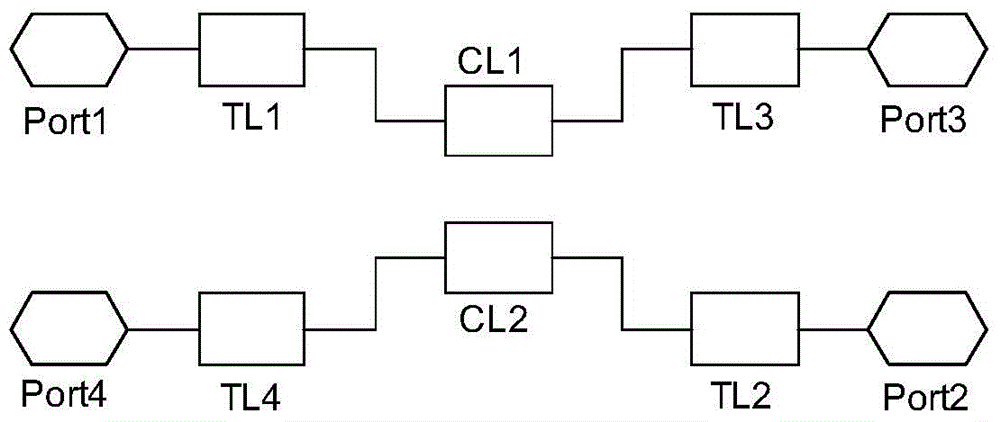
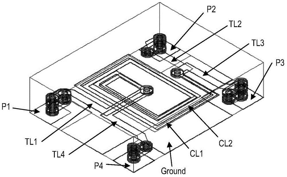
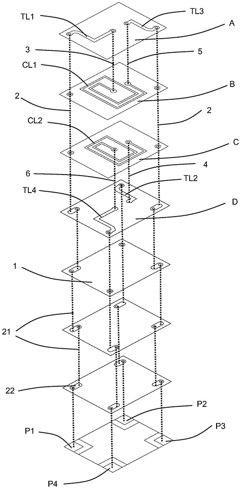
[0039] Such as figure 1 , figure 2 and image 3 Shown, chip type LTCC miniature 3dB directional coupler of the present invention is the substrate 1 that several layers are made by high-frequency low-loss dielectric material, the asymmetrical stripline that is printed on setting substrate 1 and coupling stripline and The ground terminal arranged on the upper and lower sides of the directional coupler constitutes.

[0040] The directional coupler of the present invention is a four-port device, which are respectively the first port P1, the second port P2, the third port P3 and the fourth port P4 printed with a 50 ohm impedance input, and these four ports are respectively arranged in sequence. The four corners of the bottom surface of the bottom substrate 1 .

[0041] The asymmetric stripline is divided into a first asymmetric stripline TL1, a second asymmet...


PUM

PropertyMeasurementUnit
Bandwidthaaaaaaaaaa

Abstract

The invention discloses a sheet type LTCC miniaturized 3dB directional coupler which is wide in frequency band, small in size, stable in temperature performance, small in insertion loss, balanced in amplitude and good in phase balance characteristics. The sheet type LTCC miniaturized 3dB directional coupler comprises four ports which are printed at the four corners on the bottom surface of a first bottom substrate and are provided with impedance input of 50 ohms, i.e., an input port, a straight-through port, a coupling port and an isolation port. The input port and the straight-through port are connected with a first coupling band-shaped wire on a second substrate through a first asymmetric band-shaped wire and a third asymmetric band-shaped wire which are arranged on the same substrate. The coupling port and the isolation port are connected with a second coupling band-shaped wire on a third substrate through a second asymmetric band-shaped wire and a fourth asymmetric band-shaped wire which are arranged on the other same substrate. The first coupling band-shaped wire and the second band-shaped wire represent rotary-shaped patterns and are coupled in a band-shaped mode at upper wide edges and lower wide edges. According to the invention, the coupling wires represent the rotary-shaped patterns so that quite large coupling wire length can be obtained on a limited substrate area, thus a quite wide frequency scope is obtained. The sheet type LTCC miniaturized 3dB directional coupler has the advantages of simple structure, high yield, good batch consistency and low cost.

Description

technical field [0001] The invention relates to a microwave component used for wireless communication or radar sending and receiving signals, in particular to a chip type LTCC (also known as low temperature co-fired ceramic technology) miniature 3dB directional coupler. Background technique [0002] Microwave directional couplers are used in radio frequency and microwave transmission systems to distribute, synthesize, power sample and detect the power of transmission signals, and are important components of balanced amplifiers, analog and digital phase shifters, analog and digital attenuators, etc. part. The standard microwave directional coupler is a four-port network that divides the input signal power into two output signals with a certain ratio within the set frequency range. When the directional coupler is used to transmit the signal in reverse, it will have the effect of power synthesis. [0003] Chip LTCC miniature 3dB directional coupler is an important electronic c...

Claims


Application Information

Patent Timeline
IPC IPC(8): H01P5/18
Inventor 王卫兰
Owner SHENZHEN SUNLORD ELECTRONICS
Learn More