Unlock instant, AI-driven research and patent intelligence for your innovation.

Cold rolled tube unit

A technology of cold-rolled pipes and units, applied in the direction of metal rolling, metal rolling, metal processing equipment, etc., can solve the problems of low production efficiency, poor energy saving and consumption reduction, and low rolling speed, so as to shorten the production process, The effect of improving production efficiency and improving productivity

Inactive Publication Date: 2014-06-04
北京建莱机电技术有限公司
View PDF0 Cites 1 Cited by
  • Summary
  • Abstract
  • Description
  • Claims
  • Application Information

AI Technical Summary

Problems solved by technology

[0003] The localized products of copper tube cold rolling mills include: Ningbo, Tianjin, Guangdong, Luotong, Luoyang Mining Machinery, all of which are producing and supplying different specifications of rolling mills, but most of them are improved products based on the early design of Luokuang , did not break through the model of the old Russian rolling mill, the rolling speed is low, the movement impact is strong, the noise is loud, and it is easy to be damaged. More than 90% of them are in the production of billets, and very few can produce finished products. development needs
[0004] In order to solve the problems of low production efficiency, poor energy saving and consumption reduction, and few types of cold rolling in the cold rolling process of copper-based alloy pipes of different numbers, and completely change the situation of backward pipe cold rolling technology and equipment, a high-speed continuous, automatic control, long-term Stroke rolling, suitable for cold-rolling pipe units for cold-rolling production of copper-based alloy pipes with different numbers, but there is no report in the prior art

Method used


Image

  • Cold rolled tube unit
  • Cold rolled tube unit
  • Cold rolled tube unit

Examples


Embodiment Construction

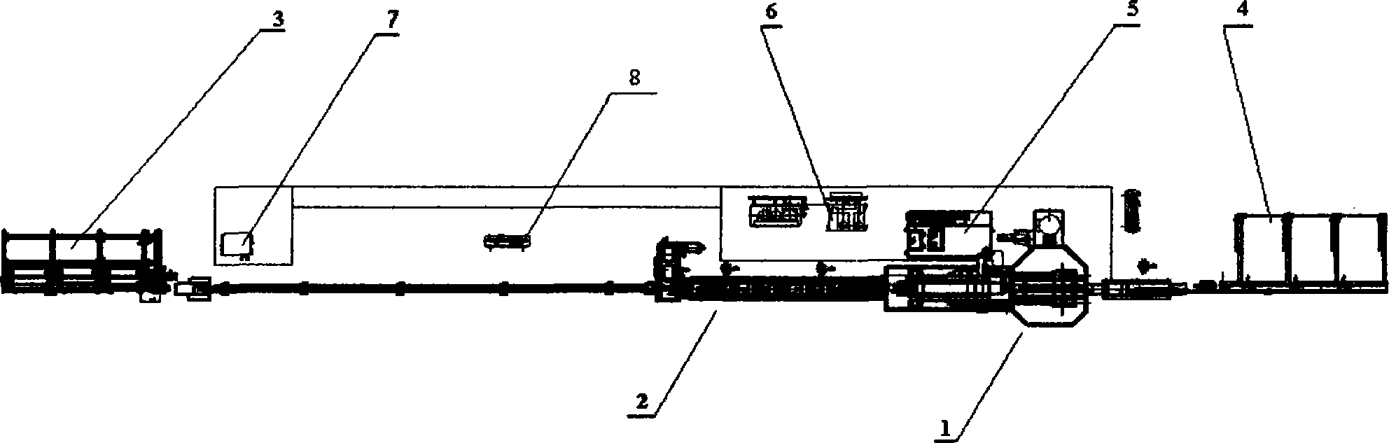
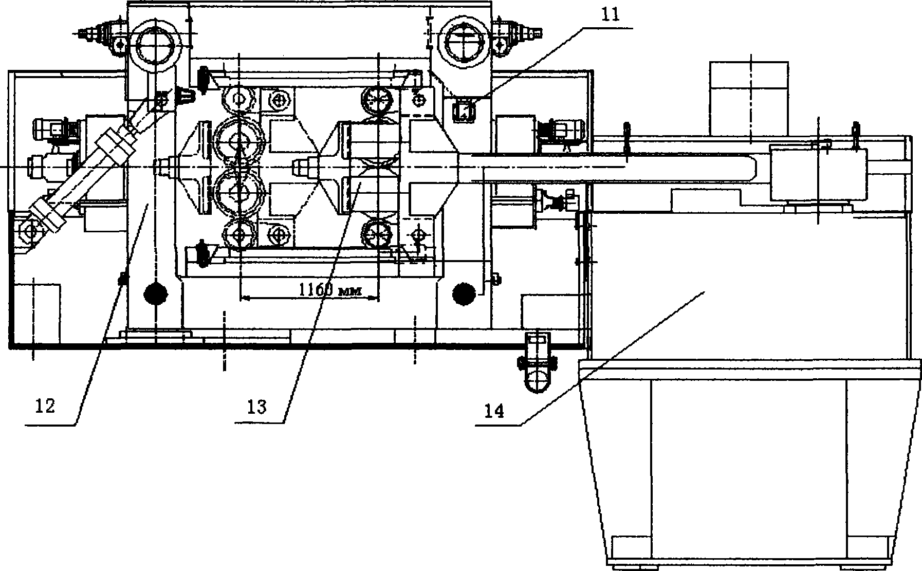
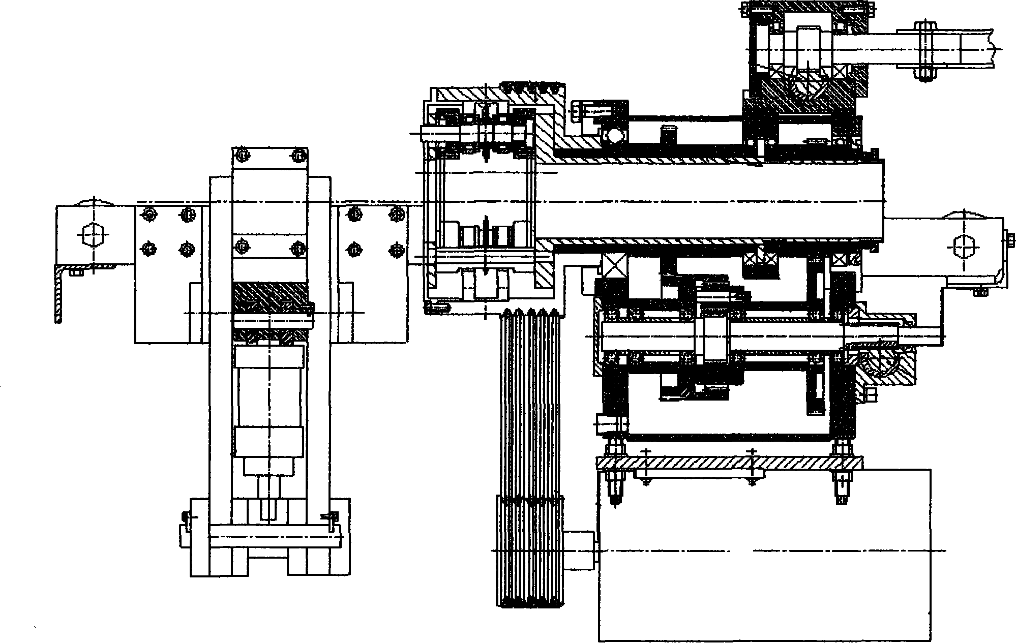
[0013] Such as figure 1 , 2 A cold-rolled pipe unit shown in , 3, including a loading platform 3 connected in sequence, a feeding section 2, a main engine 1, a short tube receiving material platform 4, and a rolling process lubrication system 5 and a hydraulic system connected with the main engine 6. Tube billet inner wall lubrication system 7, and electrical control system 8 connected to the above-mentioned sections, the main machine 1 includes a working machine base 11, a bearing arch 12, a moving roller box 13, and a main transmission box 14. The bearing The archway 12 is installed on the working machine base 11, the moving roller box 13 is installed in the working machine base 11, and the main transmission box 14 is connected with the moving roller box 13; The material roller table, the pushing trolley and the driving device; the feeding section 2 includes the rear chuck of the core rod, the feeding mechanism between the core rod chucks, the front chuck of the core rod, a...


PUM


Abstract

The invention discloses a cold rolled tube unit which comprises a loading platform, a feeding section, a main machine, a short tube receiving table, a rolling technology lubrication system, a hydraulic system, a tube blank inner wall lubricating system and an electrical apparatus control system which are connected in sequence. The rolling technology lubrication system, the hydraulic system and the tube blank inner wall lubricating system are connected with the main machine. The electrical apparatus control system is connected with all the mentioned sections. Through alternating work of a front blank chuck and a rear blank chuck, continuous feeding and rolling of a rolling mill are achieved, productivity is substantially improved, and due to continuous rolling without shutdown, production quality is more stable; a multi-pass intermediate annealing process in the traditional production technology is omitted, production technological procedure is greatly shortened, energy consumption is reduced, and production efficiency is improved; a control system achieves highly-automatic control, a man-machine interface module conveniently meets the requirement for controlling a machine of people, and the cold rolled tube unit achieves high speed, continuity, automatic control and long-stroke rolling, and is suitable for cold rolled production of copper-based alloy tubes of different specifications.

Description

technical field [0001] The invention relates to a cold-rolling pipe unit, which is mainly suitable for cold-rolling production of copper-based alloy pipes of different numbers. technical background [0002] With the development of industry and national defense technology, especially the development of aviation, automobile manufacturing, atomic energy and space technology, it is required to provide various precision thin-walled high-quality pipes with increasing quality and expanding varieties. It is one of the main means of producing precision thin-walled high-quality pipes. Therefore, all countries in the world attach great importance to pipe rolling. With the continuous deepening of reform and opening up and the country's increased investment in infrastructure construction, my country's pipe and pipeline industry has flourished in recent years, the production technology of the pipe industry has been further improved, and the scope of product application has been continuous...

Claims


Application Information

Patent Timeline
Patent Type & Authority Applications(China)
IPC IPC(8): B21B23/00B21B39/02
Inventor 高希岩王成福江津梁吴朋越高宝杰杨京朱育
Owner 北京建莱机电技术有限公司