Method and device for suppressing phase noise of long-distance optical fiber interference system based on optical path difference matching
A technology of optical fiber interference and system phase, applied in measuring devices, special recording/indicating devices, instruments, etc., can solve the problems of large phase noise and low input power, and achieve the goals of reducing phase noise, increasing maximum input power and transmission distance Effect
- Summary
- Abstract
- Description
- Claims
- Application Information
AI Technical Summary
Problems solved by technology
Method used
Image


Examples
Embodiment Construction
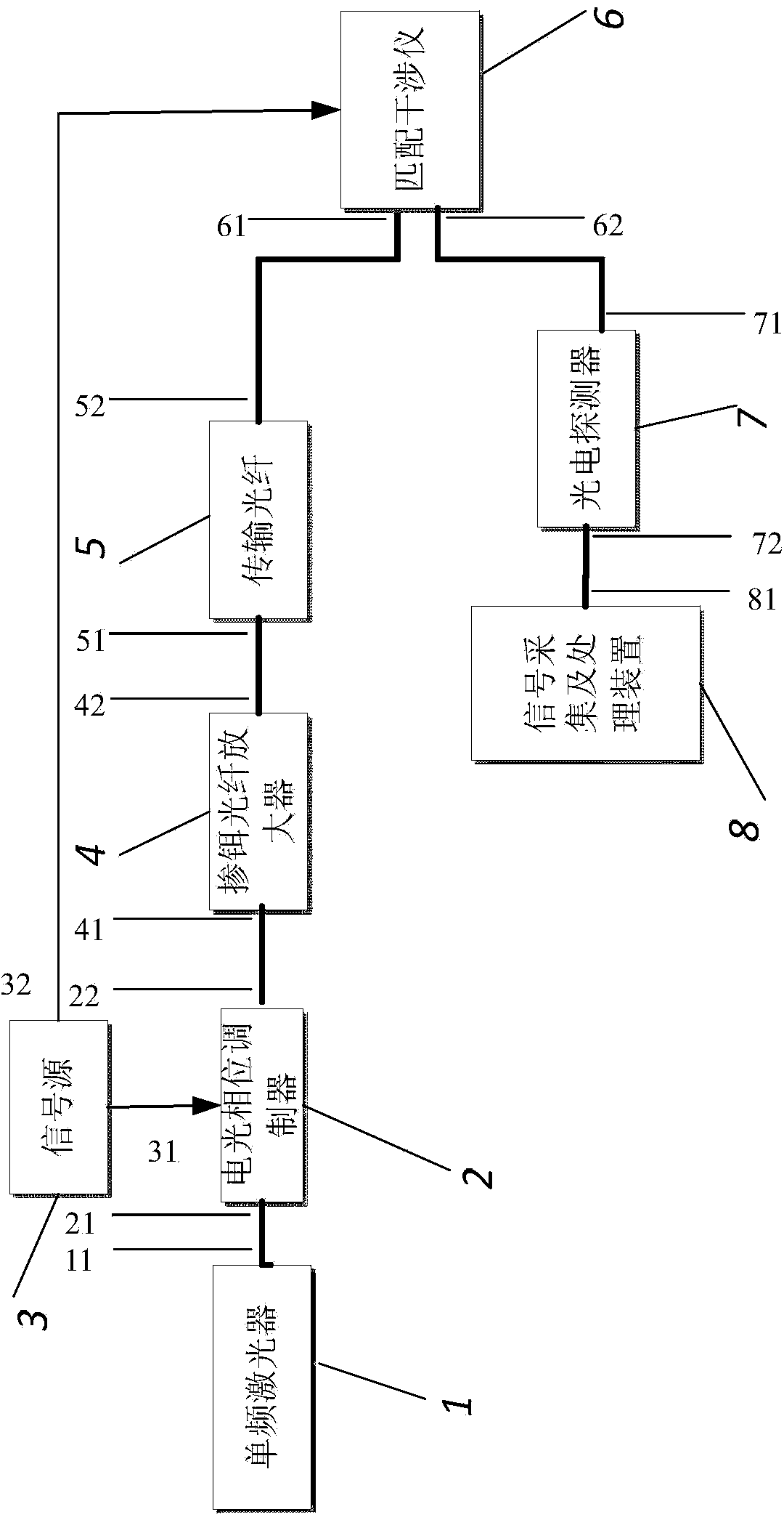
[0024] Attached below figure 1 The present invention is described further:
[0025] see figure 1 , the present invention consists of a single-frequency laser 1, an electro-optic phase modulator 2, a signal source 3, an erbium-doped fiber amplifier 4, a transmission fiber 5, a matching interferometer 6, a photodetector 7, and a signal acquisition and processing device 8. The output port 11 of the single-frequency laser 1 is connected to the input port 21 of the electro-optic phase modulator 2 through an optical fiber, and the output port 22 of the electro-optical phase modulator 2 is connected to the input port 41 of the erbium-doped fiber amplifier 4 through an optical fiber, and the erbium-doped fiber amplifier 4 The output port 42 of the transmission fiber 5 is connected to the input port 51 of the transmission fiber 5, the output port 52 of the transmission fiber 5 is connected to the input port 61 of the matching interferometer 6, and the output port 62 of the matching in...
PUM
 Abstract
Description
Claims
Application Information
 - R&D
- Intellectual Property
- Life Sciences
- Materials
- Tech Scout
- Unparalleled Data Quality
- Higher Quality Content
- 60% Fewer Hallucinations
Browse by: Latest US Patents, China's latest patents, Technical Efficacy Thesaurus, Application Domain, Technology Topic, Popular Technical Reports.
© 2025 PatSnap. All rights reserved.Legal|Privacy policy|Modern Slavery Act Transparency Statement|Sitemap|About US| Contact US: help@patsnap.com