A small flow cytometer liquid circuit system

A technology of flow cytometry and instrument liquid circuit, which is applied in the field of cell detection and analysis, and can solve the problems of difficult cleaning of sample pipelines and incorrect results, and achieve the effects of thorough and effective cleaning, reduced volume and weight, and improved detection accuracy

Active Publication Date: 2016-10-05
SUZHOU INST OF BIOMEDICAL ENG & TECH CHINESE ACADEMY OF SCI
View PDF15 Cites 0 Cited by
  • Summary
  • Abstract
  • Description
  • Claims
  • Application Information

AI Technical Summary

Problems solved by technology

This method has a good effect in reducing the volume and weight of the instrument, but on the one hand, the sample pipeline is not easy to clean; Existence is often an important factor affecting the detection accuracy, and it is also very likely to directly lead to wrong results

Method used


Image

  • A small flow cytometer liquid circuit system
  • A small flow cytometer liquid circuit system
  • A small flow cytometer liquid circuit system

Examples


Embodiment 1

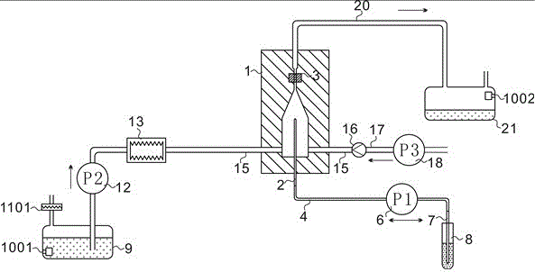
[0030] refer to figure 1 As shown, a small flow cytometer liquid circuit system allows the sample to pass through the laser detection area 3 at a certain speed and distribution width under the sheath fluid package, including the sample pipeline 4, the sheath fluid pipeline 15, the waste liquid tube Road 20 and gas pipeline 17;

[0031] A sample injection needle 2, a sample pump 6, and a sample suction needle 7 are sequentially installed on the sample pipeline 4;

[0032] One end of the sheath fluid pipeline 15 is connected to the flow chamber 1 and passes through the flow chamber 1, the other end of the sheath fluid pipeline 15 is connected to the sheath fluid pool 9, and a bladder type A filter element 13 and a sheath liquid pump 12, a first liquid level sensor 1001 is installed at the bottom of the sheath liquid pool 9, and a first filter screen 1101 is installed at the outlet of the sheath liquid pool 9 communicating with the atmosphere;

[0033] The waste liquid pipeline...

Embodiment 2

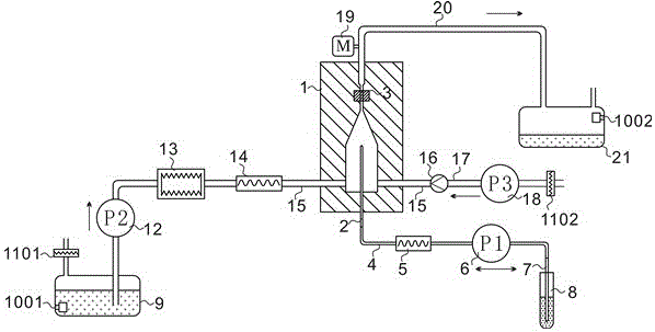
[0044] Such as figure 2As shown, the sample pipeline 4 is connected in series with the sample pump 6 and the sample pulsation buffer 5, and the sheath fluid pipeline 15 is connected in series with the capsule filter element 13, the sheath fluid pump 12 and the sheath fluid pulsation buffer 14 A pressure sensor 19 is installed at the outlet of the flow chamber 1, and a second filter screen 1102 is installed at the outlet of the micro air pump 18 communicating with the atmosphere.

[0045] The sheath fluid pulsation buffer 14 adopts one of air type, air bag type, and diaphragm type pulsation damper, and the sample pulsation buffer 5 adopts a straight-through pipeline with a smaller inner diameter, the inner diameter is less than 250 μm, or several elastic pipelines The clamper clamps the sample pipeline, and the elastic pipeline clamper includes a clamp 30 and an elastic arm 31, such as Figure 6 shown.

[0046] Since the sample flow rate is 10 μL / min-60 μL / min, the existing ...

Embodiment 3

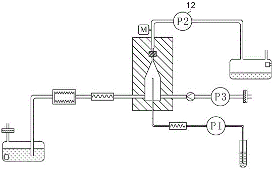
[0050] Such as image 3 As shown, the sheath liquid pump 12 is placed in the waste liquid pipeline 20, and acts as a waste liquid pump to drive the waste liquid mixed with the sample and the sheath liquid into the waste liquid pool. The flow of the sheath fluid is driven by the pressure difference between the sheath fluid pump 12 and the sample pump 6 .


PUM


Abstract

The invention discloses a miniature flow cytometer fluid path system. The system comprises a flowing chamber, a sample pipeline, a sheath fluid pipeline, a waste fluid pipeline and a gas pipeline. A sample to be tested is conveyed via a small-flow peristaltic pump and then flows into the flowing chamber after passing through a pulse buffer; sheath fluid is conveyed via a large-flow peristaltic pump or a diaphragm pump and then unilaterally or symmetrically flows into the flowing chamber after passing through a bag type filter element and the pulse buffer; a miniature air pump is connected to the flowing chamber via an one-way valve so as to remove pipeline bubbles. A pressure sensor is mounted at the exit of the flowing chamber and is used for monitoring pressure change and abnormity. A liquid level sensor is arranged in each of a sheath fluid pool and a waste fluid pool and is used for setting a liquid level alarm. A filter screen is mounted at the atmospheric connection part of the sheath fluid pool and the miniature air pump to prevent impurities from entering. Through the omission of an air pressure pump in a traditional miniature flow cytometer, the miniature flow cytometer fluid path system is simple in structure and convenient to clean, has the function of removing bubbles and can meet the application requirement on miniaturization of the miniature flow cytometer.

Description

technical field [0001] The invention relates to the technical field of cell detection and analysis, in particular to a small flow cytometer liquid path system. Background technique [0002] Flow cytometer is an instrument capable of multi-parameter, quantitative analysis or sorting of cells or biological particles in a fast-flowing state, and has been widely used in clinical medicine, cytology, biology, microbiology And other fields, known as the CT of the cell biology laboratory. As one of the important components of the flow cytometer, the fluid circuit system is used to focus on the position of the cells or particles to be detected by using the principle of fluid dynamics, so that they pass through the laser detection area one by one. The cells to be tested are prepared into a single cell suspension, labeled with a fluorescent dye, placed in a sample tube, and enter the flow chamber under pumping pressure to form a sample flow; the sheath fluid is the matrix fluid that a...

Claims


Application Information

Patent Timeline
Patent Type & Authority Patents(China)
IPC IPC(8): G01N15/14
Inventor 马玉婷裴智果陈忠祥钟金凤王策武晓东
Owner SUZHOU INST OF BIOMEDICAL ENG & TECH CHINESE ACADEMY OF SCI
Why Eureka
Try Eureka