
Silicate luminescent material and preparation method thereof

A technology of luminescent materials and silicates, applied in luminescent materials, chemical instruments and methods, etc., can solve the problems of shortening the service life of field emission devices, reducing the luminous efficiency of phosphors, and need to be improved and improved, and achieves broad production and application prospects. , the effect of improved luminous performance and simple manufacturing process

Active Publication Date: 2016-03-30
OCEANS KING LIGHTING SCI&TECH CO LTD +2
View PDF3 Cites 0 Cited by
  • Summary
  • Abstract
  • Description
  • Claims
  • Application Information

AI Technical Summary

Problems solved by technology

For sulfide and sulfur oxide series phosphors, the luminous brightness is high and has certain conductivity, but it is easy to decompose under the bombardment of high-current electron beams, releasing elemental sulfur to "poison" the cathode needle tip and generate other phosphors. The sediment covers the surface of the phosphor, which reduces the luminous efficiency of the phosphor and shortens the service life of the field emission device
Oxide and silicate phosphors have good stability, but the luminous efficiency is not high enough, and the material is generally an insulator, and the performance of both needs to be improved and improved

Method used


Image

  • Silicate luminescent material and preparation method thereof

Examples


Embodiment 1

[0025] Preparation of Gd by High Temperature Solid State Method 1.95 (Si 0.999 sn 0.001 ) SiO 5 :Tb 0.05

[0026] Weigh Gd 2 (CO 3 ) 3 1.9286g, SiO 2 0.2401g, SnO 2 0.0006g, Tb 2 (CO 3 ) 3 0.0497g, placed in an agate mortar and thoroughly ground to mix evenly, then the powder was transferred to a corundum crucible, in a tube furnace in pure H 2 Sintering at 1100°C for 6h in a reducing atmosphere and cooling to room temperature to obtain Gd 1.95- (Si 0.999 sn 0.001 ) SiO 5 :Tb 0.05 Silicate luminescent material.

Embodiment 2

[0028] Preparation of Y by high-temperature solid-phase method 1.92 (Si 0.997 sn 0.003 )O 5 :Tb 0.08

[0029] weigh Y 2 o 3 0.8670g, SiO 2 0.2396g, SnO 2 0.0018g, Tb 4 o 7 0.0598g, put it in an agate mortar and grind it until it is evenly mixed, then transfer the powder to a corundum crucible, and place it in a tube furnace at 95v%N 2 +5v%H 2 Sintering at 1200°C for 2 hours in a weak reducing atmosphere and cooling to room temperature to obtain Y 1.92 (Si 0.997 sn 0.003 )O 5 :Tb 0.08 Silicate luminescent material.

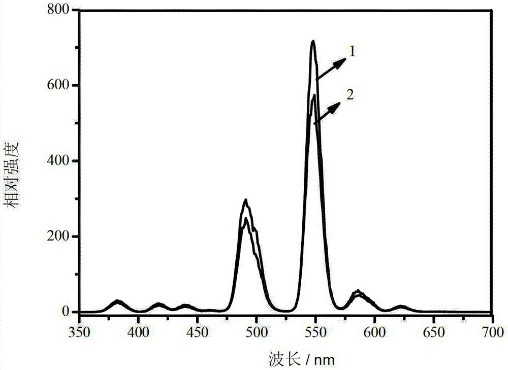
[0030] figure 1 It is a comparison chart of the luminescence spectra of the silicate luminescent material prepared in Example 2 and the comparative luminescent material under the excitation of cathode rays at an accelerating voltage of 3KV; wherein, Curve 1 is the silicate luminescent material prepared in Example 2: adding SnO 2 After Y 1.92 (Si 0.997 sn 0.003 )O 5 :Tb 0.08 The luminescent spectrum of the luminescent material; Curve 2 is a co...

Embodiment 3

[0033] Preparation of Sc by high temperature solid state method 1.90 (Si 0.999 In 0.001 )O5 :Tb 0.10

[0034] Weigh Sc 2 (CO 3 ) 3 1.0257g, SiO 2 0.2401g, In 2 o 3 0.0005g, Tb 2 (CO 3 ) 3 0.0995g, put it in an agate mortar and grind until it is evenly mixed, then transfer the powder to a corundum crucible, sinter in a tube furnace at 1000°C for 8h in a CO reducing atmosphere, and cool to room temperature to obtain Sc 1.90 (Si 0.999 In 0.001 )O 5 :Tb 0.10 Silicate luminescent material.


PUM


Abstract

The invention belongs to the field of luminescent materials and discloses a silicate luminescent material. The silicate luminescent material has a molecular general formula of Ln2-y(Si1-xMx)O5: Tby, and in the molecular general formula, Ln represents Y, Gd, Sc, Lu or La, M represents a metal element, M oxides are conductive, x is more than 0 and less than or equal to 0.2 and y is more than 0 and less than or equal to 0.5. The silicate luminescent material is added with the conductive M metal oxide component. Through the conductive performances of the M metal oxide component, under cathode ray, the silicate luminescent material has the luminescent properties superior to those of the silicate luminescent material without the conductive component so that luminescence efficiency is improved.

Description

technical field [0001] The invention relates to a luminescent material, in particular to a silicate luminescent material and a preparation method thereof. Background technique [0002] In recent years, field emission devices have attracted much attention due to their advantages such as low operating voltage, low power consumption, no need for deflection coils, no X-ray radiation, and resistance to radiation and magnetic field interference. The combination of field emission cathodes and luminescent materials can obtain high brightness, high The color rendering field emission light source can be used in fields such as display, various indications, and general lighting. The working principle of this field emission device is similar to that of a traditional cathode ray tube (CRT). It uses electron beams to bombard red, green, and blue three-color phosphors to emit light for imaging or lighting purposes. , operating temperature range, energy consumption and other aspects have po...

Claims


Application Information

Patent Timeline
Patent Type & Authority Patents(China)
IPC IPC(8): C09K11/79
Inventor 周明杰王荣
Owner OCEANS KING LIGHTING SCI&TECH CO LTD
Learn More