High-power nanometer friction generator and manufacturing method thereof
A nano-friction and generator technology, applied in the direction of friction generators, generators/motors, electrical components, etc., can solve the problems of neglect, difficulty in collection and utilization, etc., and achieve the effect of good friction effect and high energy output
- Summary
- Abstract
- Description
- Claims
- Application Information
AI Technical Summary
Problems solved by technology
Method used
Image
Examples
preparation example Construction
[0047] The preparation method of the above-mentioned high-power nano friction generator will be described in detail below. The method comprises the steps of:
[0048] (1) Preparation of a substrate with nanowires
[0049] ZnO nanowires are vertically grown on one surface of the substrate to obtain a substrate with nanowires.
[0050] The substrate that can be used in the present invention may be a silicon substrate, a gold-plated or chrome-plated glass substrate, or the like.
[0051] The present invention uses a conventional hydrothermal method to grow zinc oxide nanowire arrays, for example, hexamethylenetetramine (HMTA) and zinc nitrate hexahydrate (ZnNO 3 6(H 2 O)) mixture as a culture medium, at a suitable temperature such as 80-95 ° C, grow zinc oxide nanowire arrays on the silicon substrate. Specifically, in a specific embodiment, a zinc oxide seed layer with a thickness of 30-50 nm is formed on one surface of the silicon substrate by conventional sputtering. Using...
Embodiment 1
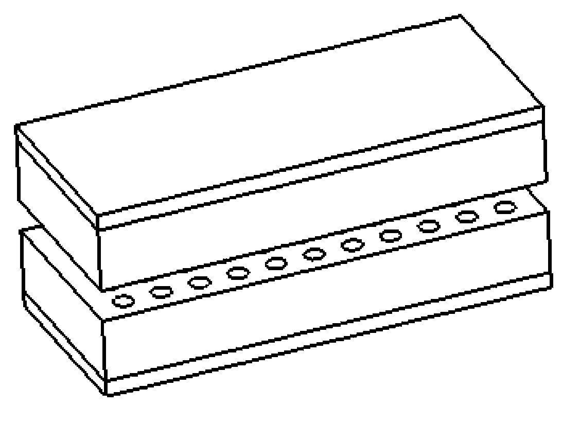
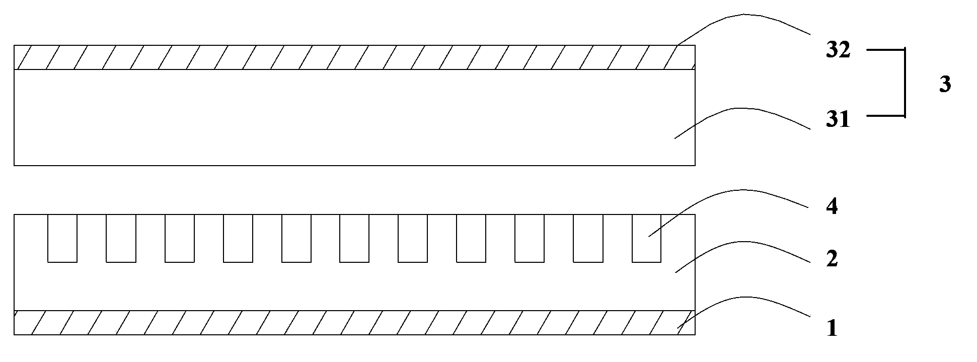
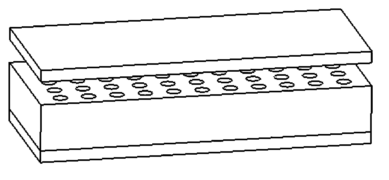
[0072] Such as figure 1 and 2 As shown, the size of the high-power nano triboelectric generator in this embodiment is 4.5cm (length) × 1.2cm (width), which includes the first electrode layer 1 (aluminum layer with a thickness of 0.1mm) stacked in sequence, high molecular polymer Layer 2 (1 mm thick polyvinylidene fluoride), and triboelectrode layer 3. The friction electrode layer 3 includes a friction film layer 31 (1.0mm thick coated paper (specification 200g / m 2 )) and a second electrode layer 32 (copper layer with a thickness of 0.1 mm), the friction film layer 31 is arranged opposite to the polymer layer 2 . The surface of the polymer layer 2 opposite to the triboelectrode layer 3 is provided with a plurality of nanopores 4 (with a width of about 60 nm, a depth of about 8 μm, and an average hole spacing of 9 μm). The first electrode layer 1 and the second electrode layer 32 are voltage and current output electrodes of the triboelectric generator.
[0073] The preparati...
Embodiment 2-3
[0084] Embodiment 2 and 3 adopt the method substantially identical with embodiment 1 to prepare, difference is listed in the following table:
[0085] Table 1
[0086]
[0087] Using a stepper motor with periodic oscillation (0.33Hz and 0.13% deformation) makes friction generator 2# and 3# undergo periodical bending and release, and the maximum output voltage and current signal of friction generator 2# reach 900V and 850μA respectively , the maximum output voltage and current signal of friction generator 3# reached 680V and 450μA respectively.
PUM
 Abstract
Description
Claims
Application Information
 - R&D
- Intellectual Property
- Life Sciences
- Materials
- Tech Scout
- Unparalleled Data Quality
- Higher Quality Content
- 60% Fewer Hallucinations
Browse by: Latest US Patents, China's latest patents, Technical Efficacy Thesaurus, Application Domain, Technology Topic, Popular Technical Reports.
© 2025 PatSnap. All rights reserved.Legal|Privacy policy|Modern Slavery Act Transparency Statement|Sitemap|About US| Contact US: help@patsnap.com


