Method for removing aluminum alloy laser welding air holes

A technology of laser welding and aluminum alloy, which is applied in the direction of laser welding equipment, welding equipment, welding/welding/cutting items, etc., to achieve the effect of improving stability, stabilizing the welding process, and avoiding collapse

Inactive Publication Date: 2014-06-18
HARBIN INST OF TECH
View PDF10 Cites 51 Cited by
  • Summary
  • Abstract
  • Description
  • Claims
  • Application Information

AI Technical Summary

Problems solved by technology

[0004] The purpose of the present invention is to solve the problem that laser welding and laser-TIG composite welding aluminum

Method used


Image

  • Method for removing aluminum alloy laser welding air holes
  • Method for removing aluminum alloy laser welding air holes
  • Method for removing aluminum alloy laser welding air holes

Examples


specific Embodiment approach 1

[0043] Specific implementation mode 1: A method for eliminating air holes in aluminum alloy laser welding according to this implementation mode, the specific operations are as follows:

[0044] Step 1: Before welding, grind or clean the surface of the workpiece to be welded, and fix the polished or cleaned workpiece to be welded on the welding fixture;

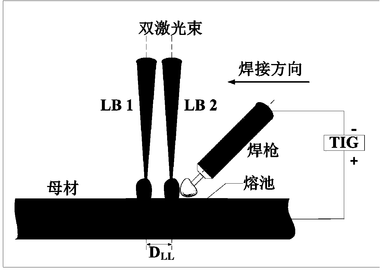
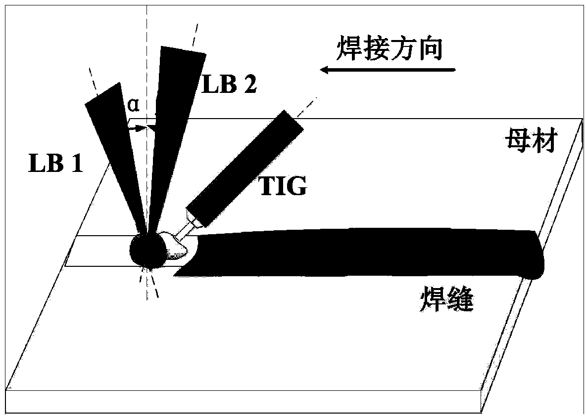
[0045] Step 2: Apply the bifocal laser and the TIG arc together on the area to be welded, set the geometric parameters: the angle between the laser beam and the vertical direction is 3°~10°, the defocus of the beam is -3mm~﹢3mm, the laser spot The diameter is 0.1~0.5mm, and the angle between the TIG welding torch and the vertical direction is 25°~55°;

[0046] Step 3: Set the welding parameters of dual-focus laser-TIG hybrid welding: the welding speed is 0.5-5m / min, the arc current is 50-150A, and the shielding gas is an inert gas;

[0047] Step 4: Start the control switch, first pass in the shielding gas, and then ignite the...

specific Embodiment approach 2

[0056] Specific embodiment 2: The difference between this embodiment and specific embodiment 1 is that if the distribution of the two laser beams is a tandem distribution along the welding direction, the dual-focus laser and TIG arc welding are divided into two types: Way:

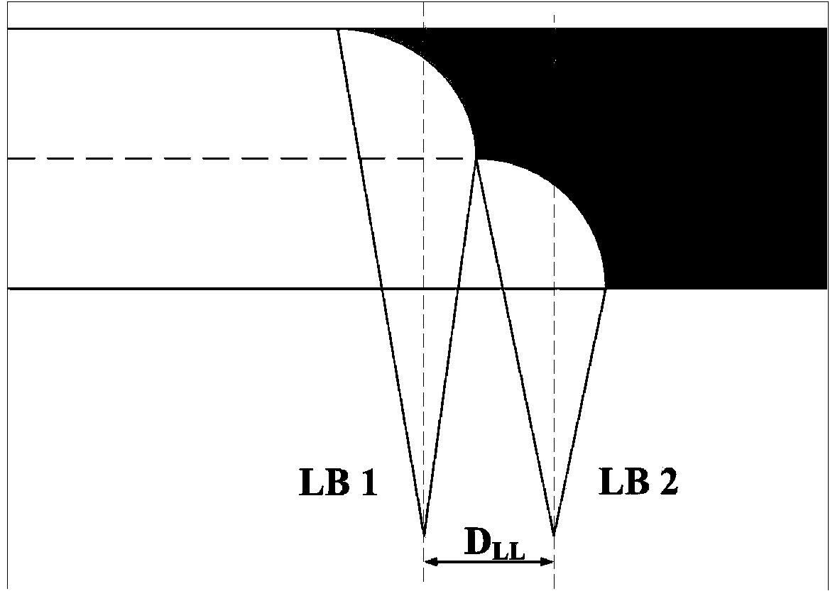
[0057] The first method (single keyhole tandem type) is: the first laser beam LB1 and the second laser beam LB2 act on the two keyholes in series at the same time, and at the same time the TIG arc is close to the second laser beam LB2 for welding; among them, The power ratio of the first laser beam LB1 to the second laser beam LB2 is (3:7)~(5:5),

[0058] The second method (double keyhole tandem type) is: the first laser beam LB1 and the second laser beam LB2 act in series at the same time in the same keyhole, and at the same time the TIG arc is welded close to the second laser beam LB2; , the power of the first laser beam LB1 is the same as that of the second laser beam LB2. Others are the same as in th...

specific Embodiment approach 3

[0059] Specific embodiment three: the difference between this embodiment and specific embodiment one or two is: if the distribution mode of the two laser beams is a parallel distribution perpendicular to the welding direction, the first laser beam LB1 of the bifocal laser and the second beam The focus of the laser LB2 is at the same part of the weld, and the TIG arc is welded at the back side of the vertical bisector of the laser beam focus line 2-4mm. Others are the same as in the first or second embodiment.


PUM

PropertyMeasurementUnit
Diameteraaaaaaaaaa

Abstract

The invention relates to a method for removing aluminum alloy laser welding air holes. The method solves the problem that air hole defects are easily generated in the laser welding and laser-TIG hybrid welding process of aluminum alloy. The method comprises the steps that in the bifocal laser-TIG hybrid welding process of the aluminum alloy, namely, in the aluminum alloy welding process, two beams of lasers (LB1 and LB2) and a TIG electric arc are adopted to jointly act on a welded area, a welding joint bears the combined action of the three heat sources at the same time, and the action modes of the two lasers can be divided into three kinds which comprise a serial distribution mode in the welding direction, a parallel distribution mode perpendicular to the direction of the welding joint and a crossing distribution mode between the serial distribution mode and the parallel distribution mode. According to the welding method, the air hole rate is zero, and air hole defects of the aluminum alloy laser welding are overcome. The method is applied to the field of aluminum alloy laser welding.

Description

technical field [0001] The invention relates to a method for eliminating air holes in aluminum alloy laser welding, in particular to welding aluminum alloys using a dual-focus laser-TIG composite welding method, and belongs to the field of material processing engineering. Background technique [0002] As we all know, aluminum alloys are widely used in the construction of welded structures due to their advantages such as light weight and high specific strength, especially in aerospace and other fields that have extremely strict weight requirements. At present, the welding methods of aluminum alloys are mainly concentrated on tungsten argon arc welding (TIG welding for short) and gas shielded welding (MIG or MAG welding for short), such as patents CN201310365187.0, CN200910064125.X, CN200810068867.5, etc., but these The production efficiency of the method is low, the formation of the weld seam is unstable, and pores are prone to occur. As an emerging technology, laser welding...

Claims


Application Information

Patent Timeline
IPC IPC(8): B23K26/348B23K26/24B23K26/60B23K28/02
CPCB23K26/24B23K26/348B23K26/60B23K2103/10
Inventor 雷正龙刘鸣陈彦宾张可召孙忠绍
Owner HARBIN INST OF TECH
Why Eureka
Try Eureka