Check patentability & draft patents in minutes with Patsnap Eureka AI!

Multipoint floating supporting device

A floating support, multi-point technology, applied in the direction of movable track, transportation and packaging, conveyor, etc., can solve the problem that the support system and the curved track cannot be reliably contacted, and achieve compact structure, increased contact surface, and large bearing capacity. Effect

Active Publication Date: 2014-06-18
HARBIN INST OF TECH
View PDF5 Cites 4 Cited by
  • Summary
  • Abstract
  • Description
  • Claims
  • Application Information

AI Technical Summary

Problems solved by technology

[0003] The present invention provides a multi-point floating support device to solve the problem that the existing arc track support system is only provided with support wheels in the vertical direction, and the support system cannot reliably contact the arc surface of the arc track.

Method used


Image

  • Multipoint floating supporting device
  • Multipoint floating supporting device
  • Multipoint floating supporting device

Examples


specific Embodiment approach 1

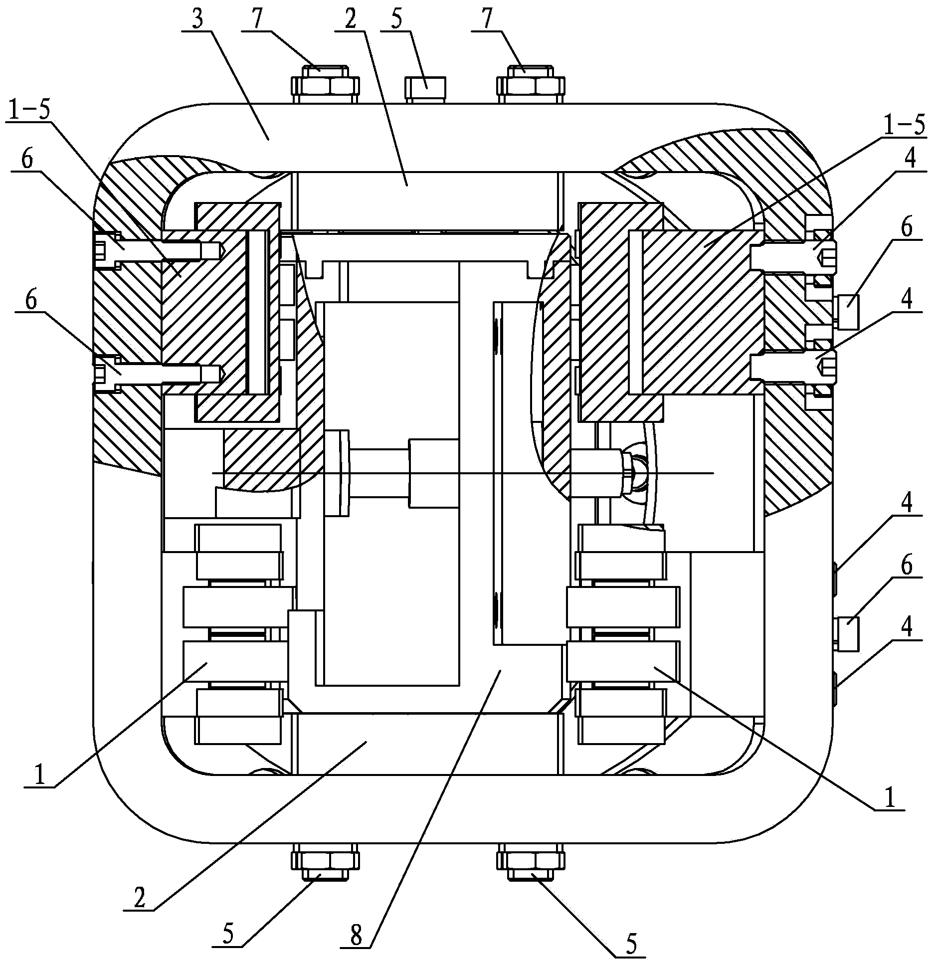
[0019] Specific implementation mode one: combine Figure 1 to Figure 8 Describe this embodiment, this embodiment includes support frame 3, two roller assemblies 2, four floating roller sets 1, four floating roller sets adjusting bolts 4, four roller assembly fixing bolts 5, six floating roller sets Fixing bolts 6 and eight roller assembly adjusting bolts 7,

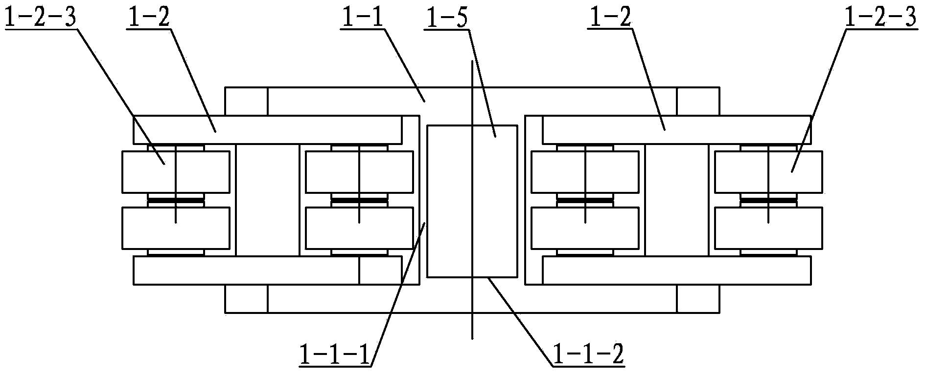
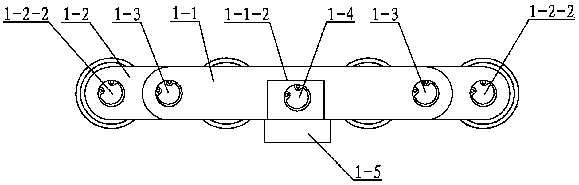
[0020] Floating roller group 1 is composed of main I-shaped frame 1-1, fixed seat shaft 1-4, fixed seat 1-5, two roller assemblies 1-2 and two roller assembly pin shafts 1-3, each roller assembly 1 -2 consists of a roller I-shaped frame 1-2-1, two roller support shafts 1-2-2 and four needle rollers 1-2-3, and the two roller support shafts 1-2-2 are symmetrically arranged on the rollers The roller I-frame vertical rib 1-2-4 two ends on the I-frame 1-2-1, and the two ends of each roller support shaft 1-2-2 are respectively connected with the roller I-frame 1-2-1 The upper and lower horizontal plates are hinged, and two ne...

specific Embodiment approach 2

[0023] Specific implementation mode two: combination figure 2 and image 3 Describe this embodiment, in this embodiment, a powder metallurgy bearing is installed between the needle roller 1-2-3 and the roller support shaft 1-2-2, and the powder metallurgy bearing can reduce the distance between the needle roller 1-2-3 and the Frictional resistance between roller support shafts 1-2-2. Other components and connections are the same as those in the first embodiment.

specific Embodiment approach 3

[0024] Specific implementation mode three: combination image 3 and Figure 4 Describe this embodiment. In this embodiment, a powder metallurgy bearing is installed between the roller I-frame 1-2-1 and the pin shaft 1-3 of the roller assembly. The powder metallurgy bearing can reduce the number of roller I-frames 1-2-1 and Frictional resistance between pins 1-3 of the roller assembly. Other compositions and connections are the same as those in Embodiment 1 or 2.


PUM

PropertyMeasurementUnit
Radianaaaaaaaaaa
Radianaaaaaaaaaa
Radianaaaaaaaaaa

Abstract

The invention provides a multipoint floating supporting device, and relates to a rail supporting system. The multipoint floating supporting device solves the problem that an existing arc-shaped supporting system is only provided with supporting wheels in the vertical direction. Two roller assemblies are arranged on the inner side wall of an upper transverse frame and the inner side wall of a lower transverse frame of a supporting framework, the roller assembly on the upper transverse frame is connected with the supporting framework through two roller assembly fixing bolts and four roller assembly adjusting bolts, and the roller assembly on the lower transverse frame is connected with the supporting framework through two roller assembly fixing bolts and four roller assembly adjusting bolts. Two floating rolling wheel sets are arranged on the inner wall of a left vertical frame of the supporting framework, and each floating rolling wheel set on the left vertical frame is connected with the supporting framework through two floating rolling wheel set fixing bolts; two floating rolling wheel sets are arranged on the inner wall of a right vertical frame of the supporting framework, and each floating rolling wheel set on the right vertical frame is connected with the supporting framework through a floating rolling wheel set fixing bolt and two floating rolling wheel set adjusting bolts. The multipoint floating supporting device is used for supporting an arc-shaped rail.

Description

technical field [0001] The invention relates to a rail support device, in particular to a multi-point floating support device. Background technique [0002] The rail support system is used to move and support large equipment on fixed rails. For example, in nuclear power plants, since the nuclear fusion reactor device is a circular cavity, it is necessary for the equipment to enter the remodeling cavity during reactor maintenance. Due to the large The equipment weighs 4t, so the arc track 8 is used to run and maintain the equipment on the arc track 8; the track is required to have a super load capacity, and it is also required to have a very high configuration control accuracy and a compact Structural size, and the friction force required to walk on the track is small. Currently, the existing arc track 8 support system is usually provided with support wheels in the vertical direction (up and down), and the support wheels in the vertical direction are fixed and cannot be adjus...

Claims


Application Information

Patent Timeline
IPC IPC(8): B65G35/00E01B23/00
Inventor 朱延河臧希喆赵杰王加
Owner HARBIN INST OF TECH
Features
  • R&D
  • Intellectual Property
  • Life Sciences
  • Materials
  • Tech Scout
  • Unparalleled Data Quality
  • Higher Quality Content
  • 60% Fewer Hallucinations
Learn More