
Wet-process ferric salt membrane-electrolysis regenerated biogas desulfurization method and device thereof

A biogas desulfurization and membrane electrolysis technology, which is applied in the field of wet iron salt membrane electrolysis regeneration biogas desulfurization and its devices, can solve the problems of low overall efficiency of desulfurization process, high temperature requirements, and no engineering applications.

Inactive Publication Date: 2014-06-18
胡明成
View PDF9 Cites 6 Cited by
  • Summary
  • Abstract
  • Description
  • Claims
  • Application Information

AI Technical Summary

Problems solved by technology

However, this desulfurization technology has the following disadvantages: the temperature requirements are relatively high, because the optimal temperature range of sulfur bacteria is 25-40 ° C, so in order to maintain the high efficiency of desulfurization, it is necessary to keep warm or run with heat
Using this desulfurization process requires power or purified biogas as a heat source to maintain the temperature required for the regeneration process, so the overall efficiency of this desulfurization process is not high
In addition, except for the first application of Bio-SR desulfurization process to waste gas desulfurization of barium chemical reagent plant, there are no related reports on its engineering application in the fields of natural gas desulfurization and biogas desulfurization

Method used


Image

  • Wet-process ferric salt membrane-electrolysis regenerated biogas desulfurization method and device thereof
  • Wet-process ferric salt membrane-electrolysis regenerated biogas desulfurization method and device thereof
  • Wet-process ferric salt membrane-electrolysis regenerated biogas desulfurization method and device thereof

Examples


Embodiment Construction

[0025] The specific implementation of the present invention will be described in conjunction with the examples.

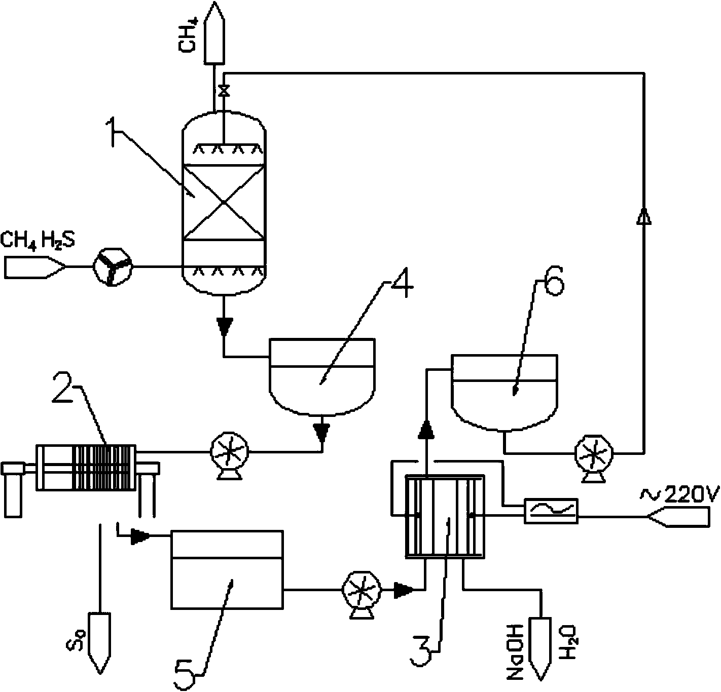
[0026] like figure 1 As shown, the wet-process iron-salt membrane electrolysis regeneration biogas desulfurization device includes an absorption tower 1, the waste liquid outlet of the absorption tower 1 communicates with the water inlet of the separation device 2 through the recovery tank 4, and the water outlet of the separation device 2 passes through the buffer tank 5 and The water inlet of the diaphragm electrolyzer 3 is connected, and the water outlet of the diaphragm electrolyzer 3 is connected with the water inlet of the absorption tower 1 through the liquid storage tank 6 .

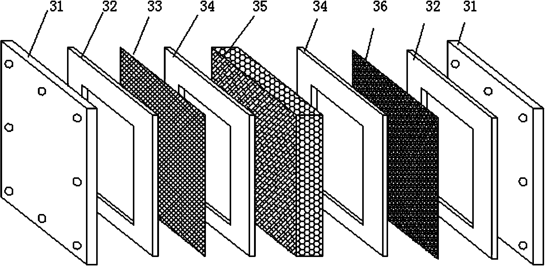
[0027] like figure 2 As shown, the diaphragm electrolyzer 3 includes a casing, a power supply, and two end plates 31 and sealing gaskets 32. The end plate 31 is an electrolyzer, and the electrolyzer includes a cathode plate 33 and an anode plate 36. There is a composite separation ...


PUM

PropertyMeasurementUnit
current efficiencyaaaaaaaaaa

Abstract

The invention relates to a desulfurization method and a desulfurization device, and specifically relates to a wet-process ferric salt membrane-electrolysis regenerated biogas desulfurization method and device thereof. The wet-process ferric salt membrane-electrolysis regenerated biogas desulfurization device comprises an absorption tower, wherein a waste liquid outlet of the absorption tower is communicated with a water inlet of a separating device by a recycling tank; a water outlet of the separating device is connected with a water inlet of a diaphragm electrolytic cell by a buffer tank; and a water outlet of the diaphragm electrolytic cell is connected with the water inlet of the absorption tower by the liquid storage tank. Absorption liquid which absorbs hydrogen sulfide can be recycled after being treated by the separating device and the diaphragm electrolytic cell. The whole process can be normally operated without an extra heat source under a normal temperature condition, and products are elemental sulfur sludge as well as alkali and hydrogen gas which are produced by an electrolysis regeneration process, and are free of secondary pollution. The device not only can be manufactured into a large device, but also can be manufactured into a small device, so that no matter large-scale biogas energy resource engineering or small-scale biogas energy resource engineering can adopt the desulfurization way.

Description

technical field [0001] The invention relates to a desulfurization method and device, in particular to a wet iron salt membrane electrolysis regeneration biogas desulfurization method and device. Background technique [0002] Biogas produced by anaerobic fermentation of organic waste, high-concentration organic industrial wastewater and biomass solid waste must be desulfurized before it can be used as energy. [0003] At present, the more mature desulfurization processes are as follows: [0004] Biological desulfurization, that is, THIOPAQ desulfurization technology, utilizes the metabolic activities of sulfur bacteria to convert H in biogas 2 A desulfurization technology that realizes biogas purification by converting S into simple substances. From the relevant technical data of engineering application, biological desulfurization H 2 The removal rate of S can reach 90%, and the conversion rate of sulfide into simple substance can reach 85%. However, this desulfurization ...

Claims


Application Information

Patent Timeline
Patent Type & Authority Applications(China)
IPC IPC(8): C10L3/10B01D53/78B01D53/52B01D53/96
Inventor 胡明成
Owner 胡明成
Learn More