Hydraulic transmission automatic control continuously variable transmission

A technology of continuously variable transmission and hydraulic transmission, which is applied in transmission device control, transmission box, transmission device, etc. It can solve the problems of complex mechanical structure and control system, high maintenance and repair costs, and small metal belt carrying capacity, etc., to achieve control The system is simple and reliable, the maintenance cost is low, and the rotation efficiency is high

Inactive Publication Date: 2016-06-29
枣庄市九洲快运有限公司
View PDF5 Cites 0 Cited by
  • Summary
  • Abstract
  • Description
  • Claims
  • Application Information

AI Technical Summary

Problems solved by technology

[0002] At present, the automatic transmission that is used more in automobiles is the automatic transmission that combines the hydraulic torque converter and the planetary gear system, but it has obvious disadvantages: the mechanical structure and the control system are complex, the transmission ratio is discontinuous, and the power Large loss, low efficiency, high maintenance and repair costs
Another continuously variable transmission (CVT), which uses a metal transmission belt and changes the matching diameter of the driving and driven wheels to achieve speed change and power transmission, but the weakness of CVT is that the metal belt has a small carrying capacity, limited transmission power, and high cost. short life
In addition, due to its rather complex control system, the auxiliary cost increases
Therefore, the continuously variable transmission (CVT) is currently only available in low-emission vehicles

Method used


Image

  • Hydraulic transmission automatic control continuously variable transmission
  • Hydraulic transmission automatic control continuously variable transmission
  • Hydraulic transmission automatic control continuously variable transmission

Examples


Embodiment 1

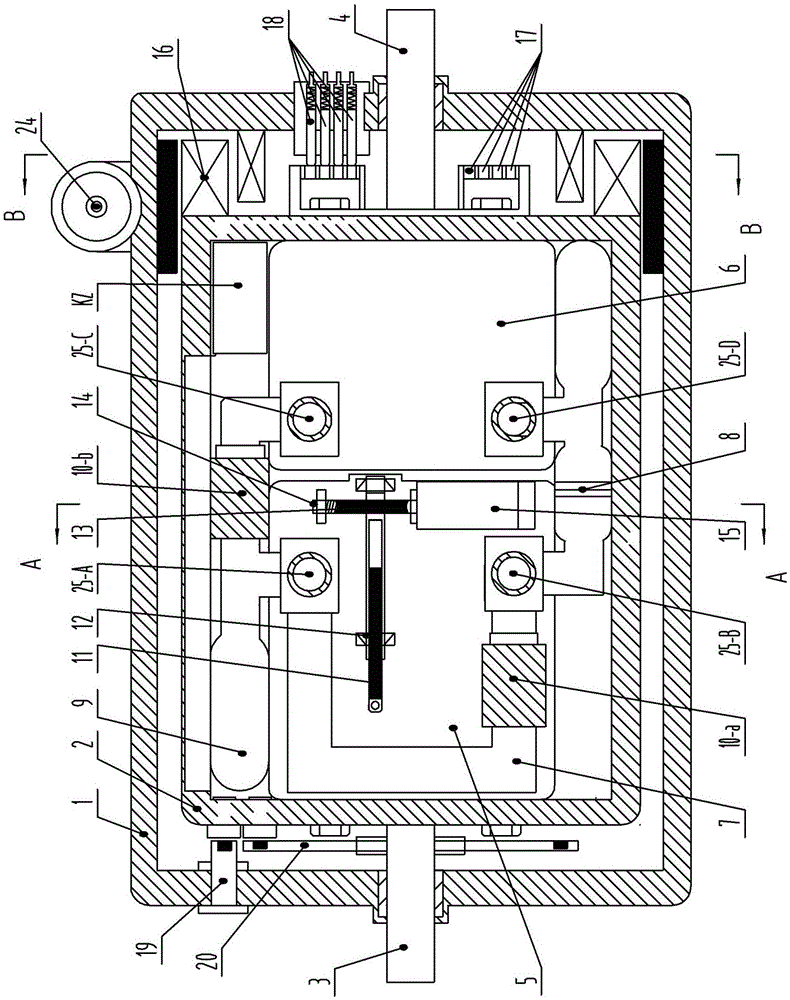
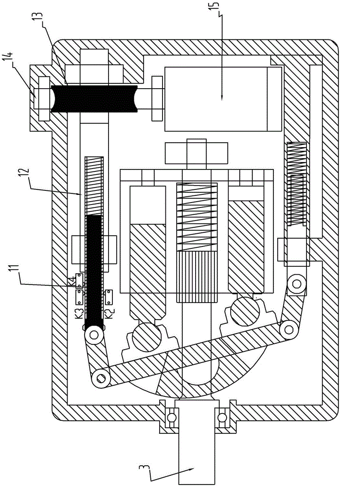
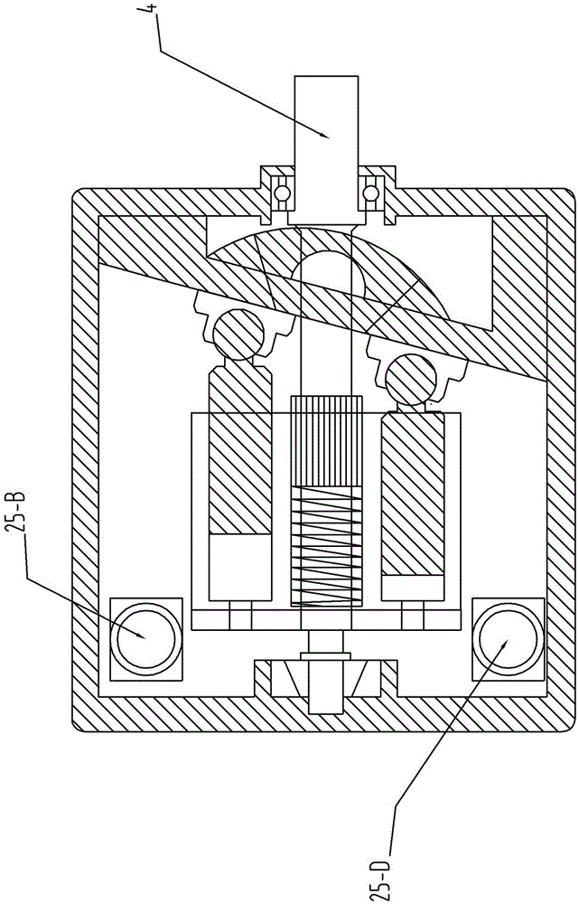
[0030] see Figure 1 to Figure 8, in the figure, the hydraulic transmission automatic control continuously variable transmission of the present invention includes a casing 1, a transmission assembly installed in the casing 1 and an overrunning clutch 16, and the transmission assembly includes an inner casing 2, an input shaft 3, an output shaft 4, two-way hydraulic Variable pump 5, quantitative hydraulic motor 6, oil passage 7, filter 8, buffer chamber 9, first and second hydraulic solenoid valves 10-a, 10-b, variable control drive screw 11, variable control screw sleeve 12, variable Control worm gear 13, variable control worm 14, variable drive motor 15, overrunning clutch 16, slip ring 17, electric brush 18, turntable (with magnet) 20 and other components. The two-way variable pump 5 and the quantitative motor 6 are installed in series in the inner shell 2. The input shaft of the two-way variable pump and the output shaft of the fixed motor are installed on the same axis. Th...


PUM


Abstract

The invention discloses a hydraulic transmission and automatic control stepless speed regulator, which comprises an enclosure, a speed regulator component, an overrunning clutch and a speed regulator component brake device, wherein the speed regulator component comprises an inner shell, a speed regulator input shaft and a speed regulator output shaft; a two-way hydraulic variable pump, a constant displacement hydraulic motor, a variable control driving device and a control system are arranged in the inner shell; the two-way hydraulic variable pump is connected in series with the constant displacement hydraulic motor; the two-way hydraulic variable pump, the constant displacement hydraulic motor and two oil passages communicated with the two-way hydraulic variable pump and the constant displacement hydraulic motor form a closed loop; a buffer cavity is connected to each of the two oil passages connected with the two-way hydraulic variable pump and the constant displacement hydraulic motor; in addition, a second hydraulic electromagnetic valve is arranged between an oil port of the two-way hydraulic variable pump and an oil port of the constant displacement hydraulic motor; a first hydraulic electromagnetic valve and the second hydraulic electromagnetic valve are electrically connected with the control system. The hydraulic transmission and automatic control stepless speed regulator is simple and compact in structure, low in manufacturing cost, continuous in transmission ratio, high in bearing capacity, high in transmission efficiency, safe, reliable and long in service life.

Description

technical field [0001] The invention relates to a hydraulic transmission transmission, in particular to a hydraulic transmission automatic control continuously variable transmission. Background technique [0002] At present, the automatic transmission that is used more in automobiles is the automatic transmission that combines the hydraulic torque converter and the planetary gear system, but it has obvious disadvantages: the mechanical structure and the control system are complex, the transmission ratio is discontinuous, and the power Large loss, low efficiency, high maintenance and repair costs. Another continuously variable transmission (CVT), which uses a metal transmission belt and changes the matching diameter of the driving and driven wheels to achieve speed change and power transmission, but the weakness of CVT is that the metal belt has a small carrying capacity, limited transmission power, and high cost. Short life. In addition, since its control system is quite c...

Claims


Application Information

Patent Timeline
Patent Type & Authority Patents(China)
IPC IPC(8): F16H39/04F16H39/06F16H61/431F16H57/02
CPCF16H39/42F16H61/431
Inventor 王俊生
Owner 枣庄市九洲快运有限公司
Why Eureka
Try Eureka