
Large-flow and low-heat-value harmful waste gas incineration disposal process

A treatment process, low calorific value technology, applied in incinerators, combustion methods, combustion types, etc., can solve the problems of harmful gas leakage, frequent ignition, large consumption, etc., to achieve stable and adjustable temperature, guaranteed residence time, and stable combustion state Effect

Active Publication Date: 2014-06-18
BEIJING AEROSPACE PETROCHEM TECH & EQUIP ENG CORP LTD
View PDF9 Cites 10 Cited by
  • Summary
  • Abstract
  • Description
  • Claims
  • Application Information

AI Technical Summary

Problems solved by technology

With the enhancement of environmental protection awareness and the upgrading of environmental protection regulations, the direct high-altitude emission of harmful gases has been explicitly prohibited by environmental protection regulations; in order to ensure the purification effect of the adsorption method, the adsorption material needs to be replaced frequently, resulting in high operating costs; the incineration temperature of catalytic incineration is low If it does not meet the national standards, the complete decomposition of harmful substances cannot be guaranteed, and the catalyst needs to be replaced, and the operating cost is high; high-temperature incineration needs to consume a large amount of fuel to maintain the temperature required for incineration, and although waste heat boilers can be used to recover heat, the overall operating cost is high. low thermal efficiency
[0004] The traditional regenerative incineration process has many shortcomings such as frequent ignition, unstable incineration conditions, and harmful gas leakage. Moreover, if the exhaust gas contains corrosive components, acid gases such as SO2, SO3, and HCl will be produced after incineration, which will corrode the regenerative material. , so it is not suitable for treating waste gas containing corrosive components

Method used


Image

  • Large-flow and low-heat-value harmful waste gas incineration disposal process

Examples


Embodiment Construction

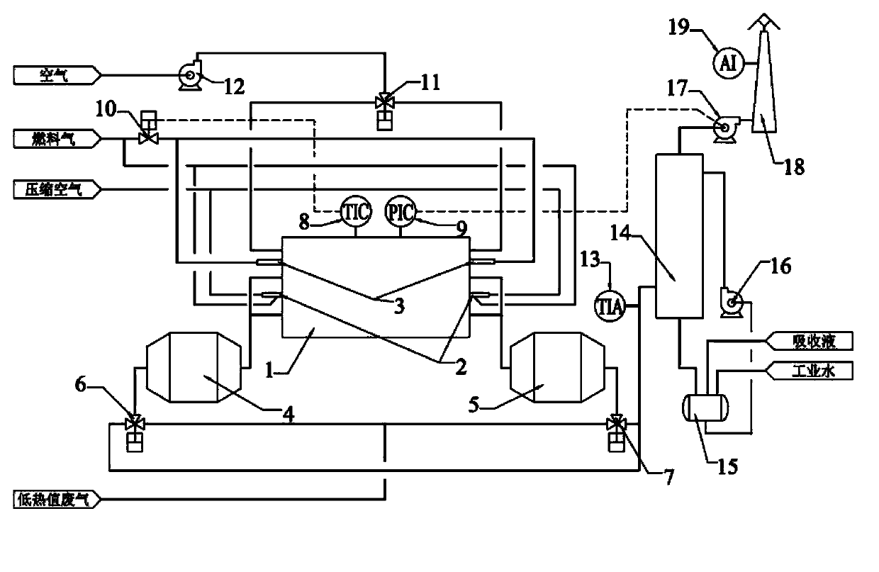
[0024] The following is an introduction to a large-flow low-calorific-value harmful waste gas incineration treatment process provided by the present invention in conjunction with the accompanying drawings and examples:

[0025] Such as figure 1 As shown, a large-flow low calorific value harmful waste gas incineration treatment process includes the following steps:

[0026] (1) The exhaust gas enters the regenerator A through the reversing valve A, and the heat stored in the regenerator in the regenerator during the previous cycle increases the temperature of the exhaust gas;

[0027] (2) The high-temperature exhaust gas after heating enters the incinerator and is incinerated under the action of the permanent lamp of the rigid flame;

[0028] (3) The furnace temperature of the incinerator is determined according to the temperature required for the decomposition of harmful components in the waste. The temperature of the furnace is measured by a temperature detection instrument....


PUM


Abstract

The invention belongs to the technical field of harmful gas treatment, particularly relates to a large-flow and low-heat-value harmful waste gas incineration disposal process, and aims to develop a novel process for treating high-air-volume and low-heat-value harmful waste gas in a regenerative combustion manner. According to the adopted technical scheme, a ceramic heat accumulating body is taken as a carrier for recovering heat of high-temperature flue gas and pre-heating waste gas, the temperature of the high-temperature flue gas falls rapidly in a heat accumulating chamber, and the heat energy is stored in the heat accumulating body and is released for heating waste gas needing to be treated in a next cylinder. The process has the beneficial effects that the system can treat waste gas containing acid components, and the temperature of flue gas is higher than the dew point temperature of acid in the heat accumulating chamber, thus corrosion to the heat accumulating body is prevented, and the emitted flue gas is up to the natural environmental protection standard; the waste gas preheating temperature can be up to 80 DEG C or higher, thereby saving over 80 percent of fuel; by adopting a rigid-flame incandescent light, stable combustion state of the system is ensured, and effective residence time of the flue gas in a hearth is ensured.

Description

technical field [0001] The invention belongs to the technical field of harmful gas treatment, and in particular relates to a process for incineration treatment of harmful waste gas with large flow rate and low calorific value. Background technique [0002] In the production process of chemical, paint, electronic products and other industries, there are often a large amount of harmful waste gas with large flow and low calorific value. The characteristics of the waste gas are: low VOC content, low calorific value, unable to maintain stable combustion, and 95% or more of the waste gas is air or Nitrogen, the temperature is basically normal temperature, the maximum flow rate is more than tens of thousands or hundreds of thousands of m3 (standard state) / h, the difference between the number of moles of flue gas produced after incineration and the number of moles of waste gas treated is less than 5%, and the waste gas often contains a small amount Hazardous waste or corrosive compo...

Claims


Application Information

Patent Timeline
IPC IPC(8): F23G7/06
Inventor 任春晓崔晓兰李超杨志刚胡广红罗剑肖伸亮罗钰李鹏飞王为伟
Owner BEIJING AEROSPACE PETROCHEM TECH & EQUIP ENG CORP LTD
Learn More