Method and device for detecting rain amount through laser

A technology of laser detection and rainfall, which is applied in measuring devices, rainfall/precipitation gauges, meteorology, etc., can solve problems such as mechanical principle limitations, rain gauge blockage, imaging changes, etc., to ensure parallelism and distribution uniformity, The effect of improving accuracy

Inactive Publication Date: 2014-06-18
KUNMING UNIV OF SCI & TECH
View PDF3 Cites 27 Cited by
  • Summary
  • Abstract
  • Description
  • Claims
  • Application Information

AI Technical Summary

Problems solved by technology

After long-term development of mechanical rain gauge, although its system and technology are relatively perfect, due to the limitation of its mechanical principle, it has some difficult problems
For example, when using a tipping bucket rain gauge to observe precipitation, there are mainly the following problems: First, the field application environment is relatively harsh. Due to the settlement of sand and dust, the accumulation of bird droppings, branches, and leaves, it is easy to block the rain gauge and affect the normal operation of the instrument. Use requires human maintenance on the equipment, and it is impossible to realize long-term unmanned automatic observation
For example, the Parsivel raindrop spectrometer, the sampling space is limited by the photoelectric array at the receiving end, and the spatial resolution is too low to detect light rain and drizzle; the FDl2P rain gauge that uses the principle of extinction scattering, the extinction coefficient is transmitted as a low-pass signal, which will be interfered by electromagnetic fields (airport); the 2DVD two-dimensional imaging rain gauge line scan camera developed by Schonhuber et al. only uses 512 photoelectric detection elements, so its resolution for small particles is low, and the physical resolution of the digital grid is 0.25mm. It cannot be measured for precipitation particles smaller than 0.5mm
In addition, existing optical rain gauges still have some common problems: ①The shape of raindrops is asymmetric when there is wind, and one-dimensional detection cannot accurately measure the size of asymmetric raindrops, and the shape of raindrops is calculated according to the spherical assumption, resulting in large errors; The light source mostly uses near-infrared light with a relatively long wavelength, so light diffraction causes large measurement errors; ③Because the thickness of the sheet light beam in the sampling area is different in the direction of light travel, for falling raindrops of the same size, When the position of the linear array detector is different, the measurement results are different, resulting in errors; ④ Since the detection light source will be affected by external conditions such as the environment during use, its output power will change with time, which will inevitably cause corresponding changes in imaging. Cause detection errors; ⑤Low scanning frequency of linear array detectors makes the time interval of scanning measurement too large, so that the representative scale of raindrops cannot be collected and measured, resulting in insufficient measurement accuracy; ⑥The pixel size of linear array detectors is too large, Measurement resolution is too low

Method used


Image

  • Method and device for detecting rain amount through laser
  • Method and device for detecting rain amount through laser
  • Method and device for detecting rain amount through laser

Examples


Embodiment 1

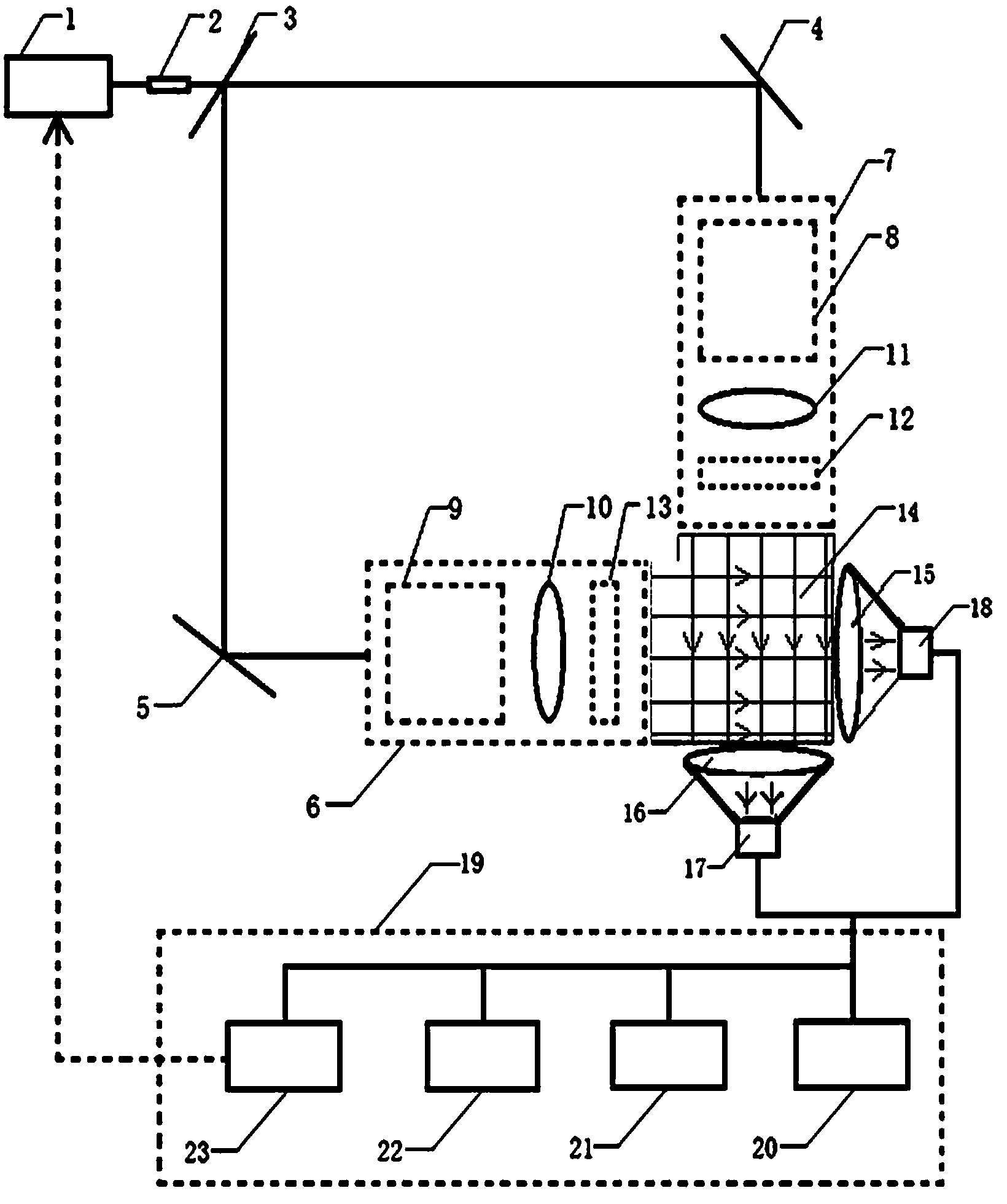
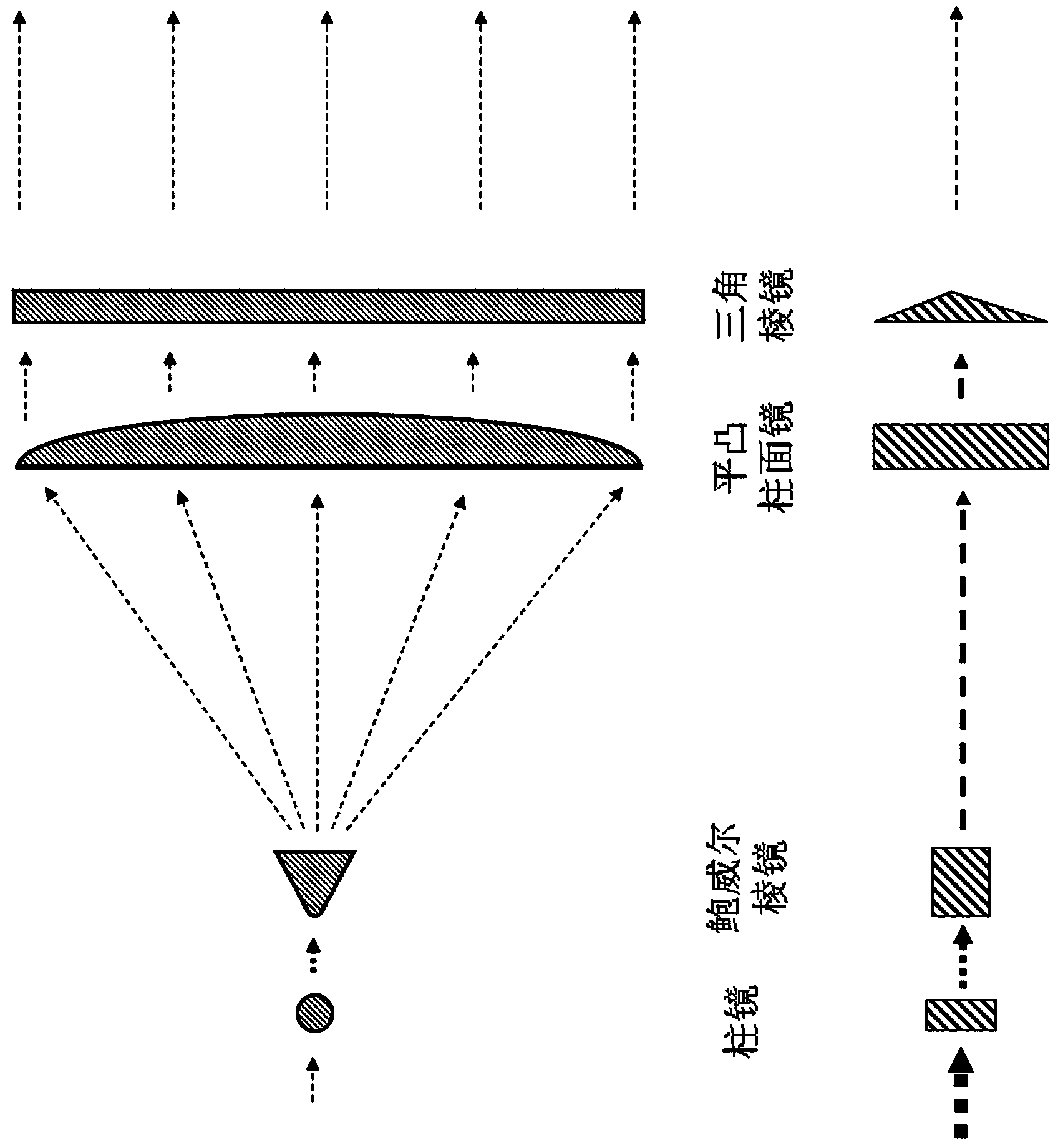
[0056] Example 1: The basic composition of the optical rain gauge system involved is as attached figure 1 As shown, it includes semiconductor laser (wavelength 405nm, power 6mW) 1, collimator 2 (diameter 6.0mm, focal length 4.7mm aspheric glass lens), beam splitter 3 (light intensity is divided into 1:1 beam splitter), mirror 4 (coated mirror with high reflectance ratio), mirror 5 (coated mirror with high reflectance ratio), parallel sheet light beam generation system 6, parallel sheet light beam generation system 7, sheet Light generator (cylindrical lens + Powell prism) 8, sheet light generator (cylindrical lens + Powell prism) 9, cylindrical plano-convex lens 10 (width 10cm, focal length 15cm), cylindrical plano-convex lens 11 (width 10cm, focal length is 15cm), triangular prism 12, triangular prism 13 (length is 12cm, width is 1cm, base angle is ), sampling space 14 (size 10cm×10cm), cylindrical convex lens 15 (width 10cm, focal length 12cm), cylindrical convex lens 16...

Embodiment 2

[0060] This embodiment uses the same optical structure as in Embodiment 1. The line array sensor adopts a CMOS high-speed line array sensor with 2048 pixels, the pixel size is 10 μm×10 μm, the acquisition line frequency is 50 kHz, and the light source adopts laser light sources of different wavelengths to compare the measurement results. Comparison. When the semiconductor lasers used are purple light (wavelength 405nm) and red light (wavelength 650nm), the same static object at the same position is measured and compared, and the two scanned grayscale profiles are obtained. The results are as follows Figure 5 shown. It can be seen from the upper figure in the figure that the result measured under purple light is closer to the actual size of the falling object, and the result is more accurate. and Figure 5 The figure below shows that when red light with a longer wavelength is used as the detection light source, the effect of light diffraction is obvious, and the measured...

Embodiment 3

[0062] In this embodiment, the difference produced by the presence or absence of a triangular prism in the parallel plate light generation system is compared, and the experiment uses an optical system similar to that in Embodiment 1.

[0063] At first considering the scope that needs triangular prism to produce effect (high concentrating parallel sheet light beam range), the triangular prism width that selects in the embodiment 1 is 1cm, and base angle is 4 ° because of the following reasons: when the width of triangular prism is constant, the triangular prism produced There is a certain functional relationship between the beam range of the high-concentration parallel plate light and its base angle. attached Image 6 Shown is the curve relationship between the beam range of the high-concentration parallel sheet light and the angle of the base angle of the triangular prism when the width is 1cm. The required sampling space in Example 1 is 10cm in size, and considering the infl...


PUM


Abstract

The invention discloses a method and device for detecting rain fall through laser. The device comprises a laser light source meeting a certain wavelength and power requirement, a parallel sheet light beam generating system based on a specified generation method, a two-dimensional water particle bidirectional sampling measurement area formed by two parallel sheets perpendicularly intersected in the horizontal direction, a linear array sensor and a rain fall detecting data processing and information feedback system. The device for detecting the rain fall through laser greatly improves the constant and stable property of detecting light and reduces measurement errors caused by light source power fluctuation. A real time humidity/ meteorological parameter sensing critical starting method is adopted. Due to the fact that calibration and correction are conducted before detection, the measurement errors caused by drifting of work points of the system can be reduced to the largest extent, and meanwhile energy consumption of a measurement system is reduced. By means of the device for detecting the rain fall through the laser, the rain fall, raininess and a raindrop spectrum can be accurately and continuously observed and measured in real time. The device for detecting the rain fall through the laser can be applied to the related fields for observing, measuring and forecasting the rain fall including weather, hydrology, high way conditions, airport taking-off and landing and the like.

Description

technical field [0001] The invention relates to a method and device for detecting rainfall and raindrop spectrum in the technical field of meteorological observation, in particular to a method and device for detecting rainfall by laser with improved detection accuracy from the aspect of optical detection. Background technique [0002] With the development of society and economy, real-time observation of precipitation plays an increasingly important role in meteorology, highways, airports, hydrology and other fields. In the field of meteorology, the weather situation is analyzed according to the observation of precipitation and the climate characteristics of various places are counted; the transportation departments such as airports and expressways formulate various emergency measures according to the precipitation situation; The observation of precipitation has become an important part of people's daily life. [0003] The existing rain gauges are mainly divided into two cat...

Claims


Application Information

Patent Timeline
Patent Type & Authority Applications(China)
IPC IPC(8): G01W1/14
CPCY02A90/10
Inventor 吴尚谦皇甫张棣刘爱英薛拓
Owner KUNMING UNIV OF SCI & TECH
Why Eureka
Try Eureka