Flow battery

A liquid flow battery and reaction solution technology, applied in fuel cells, regenerative fuel cells, circuits, etc., can solve the problems of reduced circulation flow efficiency, strong corrosion and toxicity, and low battery energy density, and achieve improved cycle efficiency and no Toxic and corrosive, abundant effect

Active Publication Date: 2014-06-18
POSITEC POWER TOOLS (SUZHOU) CO LTD +1
View PDF5 Cites 9 Cited by
  • Summary
  • Abstract
  • Description
  • Claims
  • Application Information

AI Technical Summary

Problems solved by technology

First of all, the ion concentration of the electrolyte is low, the energy density of the battery is low, and the large liquid volume will cause a large mechanical loss when the electrolyte flows, reducing the circulation flow efficiency
Secondly, the electrolyte uses a sulfuric acid solution of vanadium ions, which is highly corrosive and toxic.

Method used


Image

  • Flow battery
  • Flow battery

Examples


Embodiment 1

[0088] Positive electrode reaction solution:

[0089] Add 32 parts by volume of positive electrode active material α-manganese dioxide (average particle size is 5 μm), 3 parts by volume of positive electrode conductive agent Ketjen black (average particle size is 5 μm) into the positive electrode electrolyte (1mol / L sulfuric acid zinc solution), stir evenly to make a positive electrode reaction solution (the volume fraction of the positive electrode active material and the positive electrode conductive agent in the positive electrode reaction solution is 35%).

[0090] Negative electrode reaction solution:

[0091] Prepare the negative electrode electrolyte (4mol / L zinc sulfate solution) to make the negative electrode reaction solution.

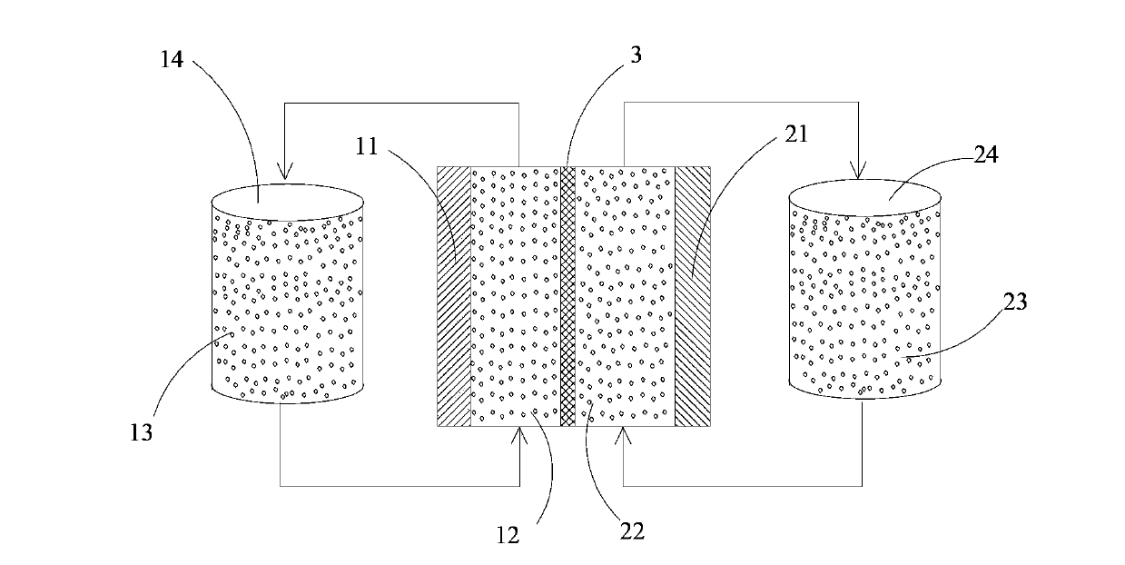
[0092] Assemble the battery:

[0093] Assemble the positive and negative electrode collectors and diaphragms to form the positive and negative electrode reaction areas, and then use pipes to connect the positive and negative electrode react...

Embodiment 2

[0095] Positive electrode reaction solution:

[0096] 24 parts by volume of positive electrode active material ZnMn 2 o 4 (the average particle size is 10 μm), 1 volume part of the positive electrode conductive agent carbon nanotube (the average particle size is 5 μm) is added in the positive electrode electrolyte (1mol / L zinc sulfate solution), stir evenly, make the positive electrode reaction solution ( The volume fraction of the positive electrode active material and the positive electrode conductive agent in the positive electrode reaction solution is 25%).

[0097] Negative electrode reaction solution:

[0098] Add 24 parts by volume of negative electrode active material zinc powder (average particle size of 5 μm) and 1 volume part of negative electrode conductive agent Ketjen black (average particle size of 10 μm) into the negative electrode electrolyte (2mol / L zinc sulfate solution) , stir evenly to make a negative electrode reaction solution (the volume fraction of ...

Embodiment 3

[0102] Positive electrode reaction solution:

[0103] 16 parts by volume of positive electrode active material ZnMn 2 o 4 (average particle size of 5 μm), 1 volume part of the positive electrode conductive agent Ketjen black (average particle size of 20 μm) was added to the positive electrode electrolyte (3mol / L zinc nitrate solution), and stirred evenly to make the positive electrode reaction solution (the volume fraction of the positive electrode active material and the positive electrode conductive agent in the positive electrode reaction solution is 17%).

[0104] Negative electrode reaction solution:

[0105] Prepare the negative electrode electrolyte (4mol / L zinc sulfate solution) to make the negative electrode reaction solution.

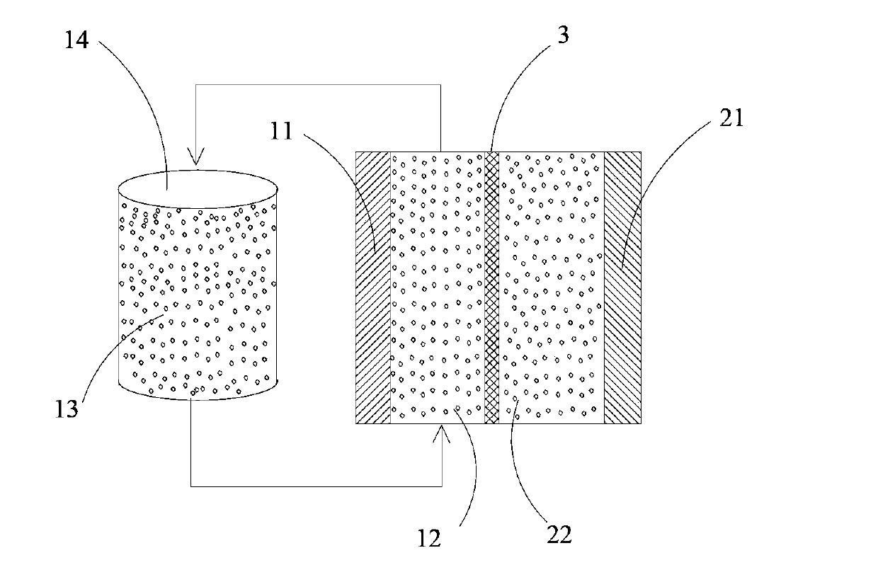
[0106] Assemble the battery:

[0107] Assemble the positive and negative electrode current collectors and diaphragms to form the positive and negative electrode reaction areas; then connect the positive electrode reaction area with the pos...


PUM

PropertyMeasurementUnit
particle sizeaaaaaaaaaa

Abstract

The invention belongs to the field of batteries, and discloses a flow battery. The flow battery comprises a positive current collector, a negative current collector, a diaphragm, a positive reaction zone, a negative reaction zone, a positive reaction solution flowing through the positive reaction zone, a negative reaction solution reacting in the negative reaction zone, a positive solution storage tank, a first power supply promoting the positive reaction solution to flow through the positive reaction zone, and a second power supply promoting the negative reaction solution to flow through the negative reaction zone; the positive reaction solution comprises a positive electrolyte, and a positive active material and a positive conductive agent suspending in the positive electrolyte; the positive active material comprises a Zn<2+>-deintercalated functional material; the negative reaction solution comprises a negative electrolyte; and the work ion of each of the positive electrolyte and the negative electrolyte is Zn<2+>. The flow battery has the advantages of high energy density and low mechanical energy consumption rate; and the electrolytes have the advantages of non-toxicity, small corrosivity, abundant raw material reserves, low price and battery cost saving.

Description

technical field [0001] The invention belongs to the field of batteries, in particular to a liquid flow battery. Background technique [0002] Since the concept of liquid flow battery was proposed in 1974, it has attracted widespread attention due to its many advantages. [0003] Liquid flow batteries are different from the solid-state active materials of ordinary batteries that are contained in the positive and negative electrodes. The positive and negative active materials of the liquid flow battery, both or one of them, are in the electrolyte contained in the liquid storage tank, and the electrolyte It flows through an inert solid electrode, and oxidation and reduction reactions occur on the surface of the inert solid electrode. Most of the flow batteries currently studied are all-vanadium flow batteries. [0004] However, the all-vanadium redox flow battery has the following disadvantages. First of all, the ion concentration of the electrolyte is low, the energy densit...

Claims


Application Information

Patent Timeline
Patent Type & Authority Applications(China)
IPC IPC(8): H01M8/18
CPCY02E60/528H01M8/188Y02E60/50
Inventor 陈璞
Owner POSITEC POWER TOOLS (SUZHOU) CO LTD
Why Eureka
Try Eureka